0
\$\begingroup\$

I have a Huzzah Feather and a 20-pin shift register TPIC6B595N. I am trying to control a multiplexed 4x4 LED matrix which I have soldered appropriately.

I am trying to figure out the proper way to wire everything up so that I don't blow an LED because soldering it was a pain in the butt.

The Huzzah is powered by a microUSB to my laptop.

My first question is how do I wire up the Huzzah and shift register properly to ground? So far, I am just connecting their respective ground pins to the negative row on my breadboard. Normally, with a power supply, I would have a positive end and a negative end but since its powered by microUSB, I'm not sure what to do here.

Second, I've connected the USB power output pin on my Huzzah to the input voltage pin on my shift register.

Third, I've connected four resistors to the outputs of the shift register and then to the positive inputs on the LED matrix.

Fourth, I've connected the negative inputs on the LED matrix to ground, the same row as described in the first step above.

Now here is where I get a little bit lost. My shift register needs a clock, data, and latch. I believe I've located where they are but can't seem to figure out what they correspond to on the Huzzah.

The Huzzah data sheet makes no mention to either of those terms.

If anyone can help me answer my questions, that'd be great. Thank you.
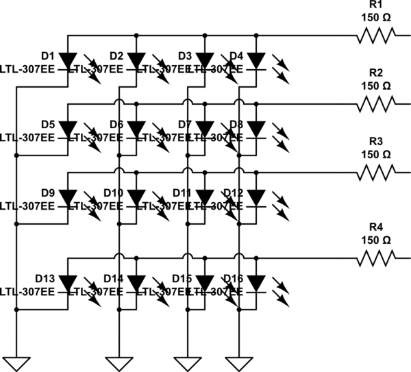
schematic

simulate this circuit – Schematic created using CircuitLab

Edit: I added the schematic of my 4x4 LED matrix as well as the resistor on the side but I couldn't figure out how to add a shift register or Huzzah Feather. Also, can someone address my question about ground? Do I just connect it to the negative row on my breadboard?

\$\endgroup\$
2
  • \$\begingroup\$ A diagram would be a lot more clear than your "sea of words". Use the built-in schematic editor (hit ctrl-M while editing your post). \$\endgroup\$
    – Dave Tweed
    Commented Jan 30, 2016 at 2:32
  • \$\begingroup\$ Okay, give me a minute while I edit. \$\endgroup\$
    – noblerare
    Commented Jan 30, 2016 at 2:37

1 Answer 1

1
\$\begingroup\$

Without a schematic, I'm not sure how you've connected your LEDs, but I doubt it's what you want.

At any rate, you'll need to specify 3 of the 9 GPIO pins on the Feather as your 3 control lines, then write a program to toggle them appropriately to shift data out to your S/R, then toggle the latch line.

\$\endgroup\$
5
  • \$\begingroup\$ I edited my post. Okay, so it's the GPIO pins that I need? Not the RX or TX, right? I was confused as to what PIN goes to what PIN. \$\endgroup\$
    – noblerare
    Commented Jan 30, 2016 at 2:50
  • \$\begingroup\$ @noblerare - Yes, use the GPIO pins. Which pin goes to which pin is entirely up to you, since you are going to write the software which drives it. You need to read the S/R data sheet and understand how to drive it. Also be aware that, with your S/R tied to USB (5 volts) power, your GPIO pins probably will not reliably drive the shift register. Read the data sheet. \$\endgroup\$ Commented Jan 30, 2016 at 2:57
  • 1
    \$\begingroup\$ @noblerare - And, now that you have shown a schematic, you have definitely wired your LEDs wrong. What you show as inputs should be tied to +5, and the S/R outputs should be connected to the LED cathodes. Also, be aware that with this connection you will only be able to display horizontal lines; that is, a single S/R bit will control 4 LEDs simultaneously, and turn all 4 on or off at the same time. \$\endgroup\$ Commented Jan 30, 2016 at 3:04
  • \$\begingroup\$ I'm not sure I follow. You're saying the output of the S/R should go into the negative ends of the LED matrix? Why would that be the case? Also, isn't the whole point of multiplexing LEDs be such that I can control them with 3 pins on the Huzzah Feather? \$\endgroup\$
    – noblerare
    Commented Jan 30, 2016 at 3:07
  • 1
    \$\begingroup\$ @noblerare - Sorry, but you're ignorant at a level I cannot address in 500 words. The S/R has "Outputs are low-side, open-drain DMOS transistors", to quote the data sheet. This means that they only work by shorting a load to ground. You need 4 high-side drivers to allow selecting which of the 4 LEDs selected by the low-side drivers is illuminated. Do research on "LED multiplexing". Good luck. \$\endgroup\$ Commented Jan 30, 2016 at 3:12

Your Answer

By clicking “Post Your Answer”, you agree to our terms of service and acknowledge you have read our privacy policy.

Not the answer you're looking for? Browse other questions tagged or ask your own question.