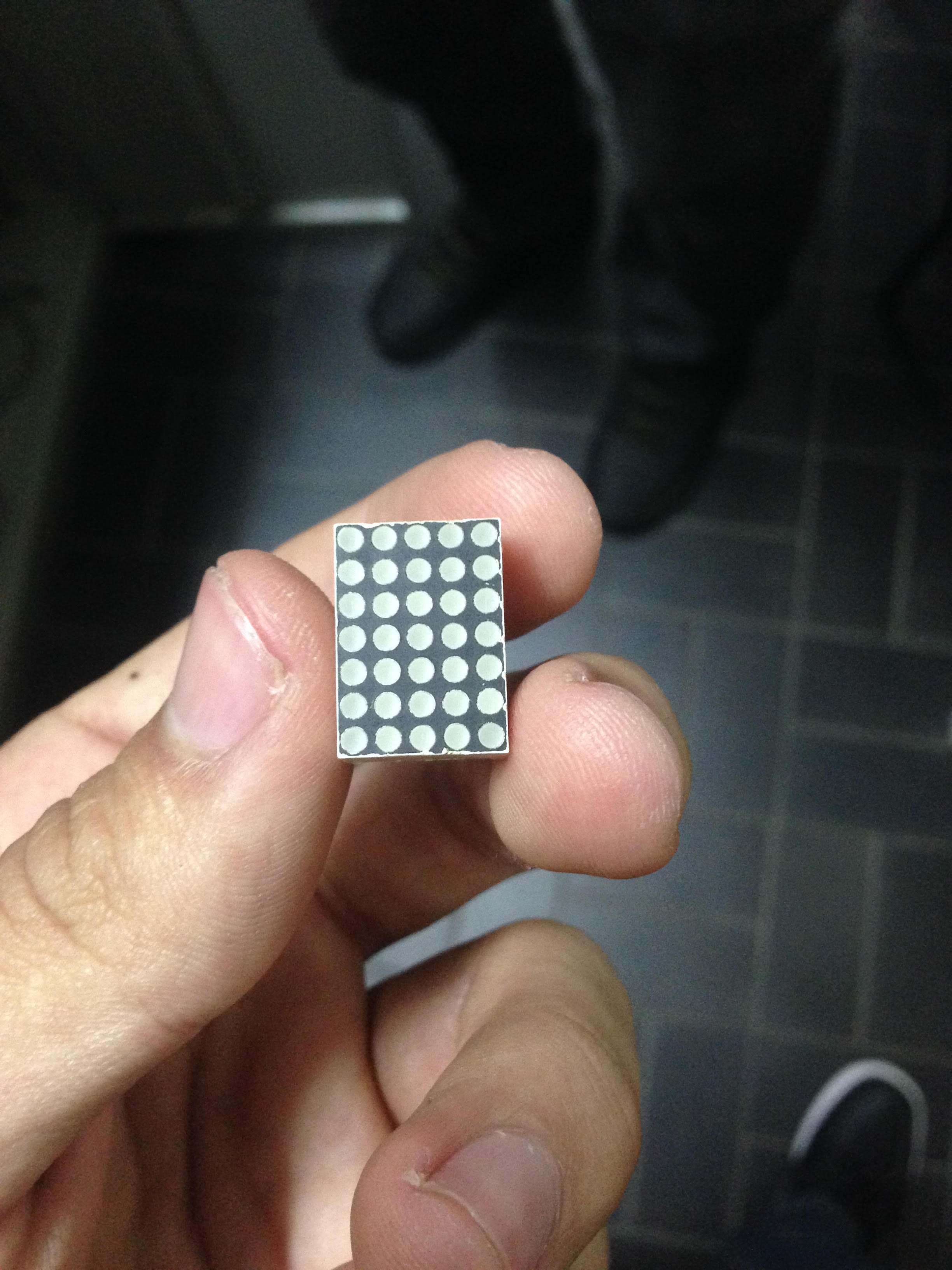
I want to know the best way to display ASCII binary code to a 7x5 LED matrix (cathode). The way I'm thinking to approach right now involves an decoder for each column (containing 7 bits, regarding the lines), and a multiplexer that receives the 35 decoded entries and outputs 7 bits. There is also a shift register in the same clock as the MUX to set HIGH in the columns the multiplexer set LOW the lines that are supposed to light. I wonder if that is the best way to do this, considering that the column decoder would be huge. Thanks for your time!
PS. Also, I forgot to mention, I am using a FPGA for this project

-
2\$\begingroup\$ The typical approach is to scan across. You have 7 pins which control the row data, and then scan along each column in turn. So a total of 12 pins. \$\endgroup\$– Tom CarpenterCommented Aug 26, 2016 at 0:15
-
\$\begingroup\$ How can I do that? with decoders for each column (with the information of the row data)? \$\endgroup\$– Victor MundurucaCommented Aug 26, 2016 at 0:21
-
\$\begingroup\$ Are you using a microcontroller? If not, what is your data source? \$\endgroup\$– Tom CarpenterCommented Aug 26, 2016 at 0:22
-
\$\begingroup\$ It's coming from a shift register, that holds 56 bits (8 letters) \$\endgroup\$– Victor MundurucaCommented Aug 26, 2016 at 0:25
-
1\$\begingroup\$ By "cathode" do you mean a vacuum fluorescent display (VFD) used mostly in the tape/cd/dvd players and set-top boxes? Would you be able to post a picture please? \$\endgroup\$– nurchiCommented Aug 26, 2016 at 0:25
3 Answers
- There is no best way without specifying constraints.
- Assuming you are only making 1 unit, the BOM cost is likely second after feature flexibility.
- Embedded processor provide flexibility far greater than combinational logic.
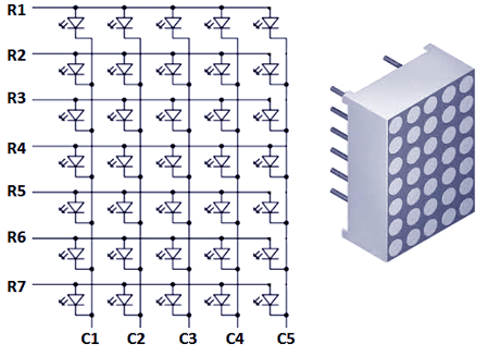
Normally, LED matrix displays such as these are not all tied to 1 common cathode. Rather, they are arranged in a matrix:
Most embedded processors have enough programmable GPIO pins to drive such a display. Here is a project in which an Atmel embedded processor (Arduino) is used to drive an 8 x 8 LED matrix.
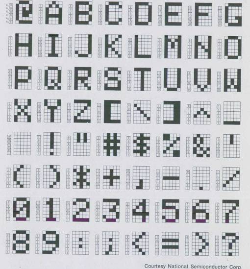
Once built, you can program the embedded processor to display your ASCII data in any number of ways. As 5 binary 7 bit numbers in each of the 5 vertical columns. As a graphical character as defined by this table:
Since an embedded processor is being used, you imagination is free to create any pattern to represent your data.
If you are using a FPGA like you said, then I would not use any external component, as the FPGA can handle this by itself.
I would simply use a signal that holds the values of each pixel (each dot of the matrix). Then I would make a clocked process that would scan through the lines (or columns) fast enough so the flickering is not visible to the human eyes.
It's basically like driving a 7-segment display except it has more pixels and you must deal with multiple common cathodes (or anodes depending on how the matrix is built).
-
\$\begingroup\$ That's what I was doing so far, I think it'll work, thanks! \$\endgroup\$ Commented Aug 26, 2016 at 14:44
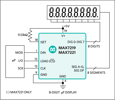
The Maxim MAX7219 and MAX7221 were purpose-designed for 8x8 LED matrix displays. They are quite popular for exactly this application.


