0
\$\begingroup\$

I am building a very simple Series circuit with a better (9V), two LEDs (Red, 5mm) and a resistor (220Ω). See the circuit below.

Now, when I connect it all together, here is what happens:

1) (+), LED1, LED2, Resistor, (-): only LED1 lights up (that's the example on the picture)

2) (+), Resistor, LED1, LED2, (-): both LEDs light up

3) (+), LED1, Resistor, LED2, (-): both LEDs light up

So turns out, my circuit doesn't work when the resistor is connected directly to (-).

I have been told that in such simple circuit it doesn't matter where is the resistor.

Does anyone have an explanation to this?

Thank you! :)
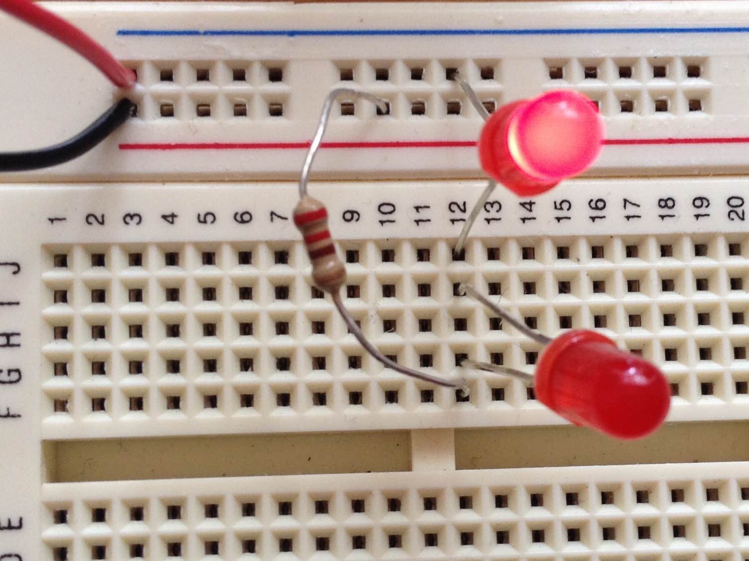
Series Circuit

\$\endgroup\$
2
  • \$\begingroup\$ David's answer is correct, but I wanted to point out that you should probably connect the red (positive) wire to the row of pins with the red line next to it. The black (negative) wire would then connect to the outside row with the blue line. Color coordination makes it easier to look at your circuit. \$\endgroup\$
    – Adam Haun
    Commented Mar 2, 2015 at 5:27
  • \$\begingroup\$ Make sense, thanks. Never understood why the line was blue and not black, it seems counterintuitive to me. \$\endgroup\$ Commented Mar 3, 2015 at 5:28

1 Answer 1

4
\$\begingroup\$

All of the pins in Row 12 are connected, so the current flows directly from LED 1 to the resistor, without traversing the 2nd LED. Put the lower lead of the 2nd LED and the lead of the resistor into another row and that will force the current to flow through the 2nd LED, lighting it.

\$\endgroup\$
1
  • \$\begingroup\$ Ahhh I didn't know that: well, that was so easy! Thank you so much :) \$\endgroup\$ Commented Mar 2, 2015 at 5:30

Your Answer

By clicking “Post Your Answer”, you agree to our terms of service and acknowledge you have read our privacy policy.

Not the answer you're looking for? Browse other questions tagged or ask your own question.