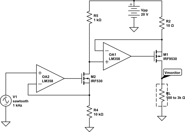
I'm designing a circuit for driving multiple loads (min. 16, up to 64) like the one shown below

simulate this circuit – Schematic created using CircuitLab
The input source is from a multi-channel DAC driven by an ATMega-like uC that can range from 0 to 5 V, and it should be able to generate a sawtooth with a minimum frequency of 1 kHz. As for the maximum frequency, this will be a trade-off between the resolution and speed of the scan. With this design, the circuit should be able to provide up to 50 mA to the load. The load resistance can vary from 100 to 3000 Ohm.
The problem is, I need to know accurately how much power is delivered to the load and I have a tight requirement of max 100 mW for each. For this reason, I'd like to introduce a monitor on the voltage using a multi-channel ADC and send it back to the uC. In this way, besides having a power monitor, I'd have a closed-loop feedback for better control. However, I'm afraid that placing the monitor in this way would cause a number of issues:
- (minor) Output resistance of the current source would be affected by the monitor (e.g. using a voltage divider before the ADC)
- (major) Need to share the SPI bus between the DAC and the ADC, lowering the maximum frequency I can obtain.
Before considering another uC, do you have any suggestion on how you would implement such functionality? Would you also consider the possibility to disable the monitoring for open-loop control?

