0
\$\begingroup\$

I have a project to build heating element using silver ink.
My specification is the heating element must be in range 2 to 2.6ohm
I will design the circuit for the heating element, but have a problem
how to theoretically measure the resistance of the circuit(before send to print house).

Based on reference on this website

http://circuitcalculator.com/wordpress/2006/06/14/conductive-ink-traces/

the resistance can be measure as below
Resistance = Sheet_Resistivity*(Length/Width)*(Ref_Thickness/Thickness)
In my case,
Sheet Resistivity = 10miliohms/square,
Ref_Thickness = 1mil(0.025mm)
Thickness = 1mil(0.025mm)

1) Based on the quotation, if I have 50mm x 50mm & another one is 10mm x 10mm
silver ink with same thickness, the ohm will be the same which is 10miliohms.
Is it logic?

2) Another question is, how to measure the resistance if I design a complicated
circuit as per attached image? In the image, 1box considered as 1mm x 1mm
Point "A" and point "B" will be connected to battery(+ve & -ve).
Blue color indicate the silver ink
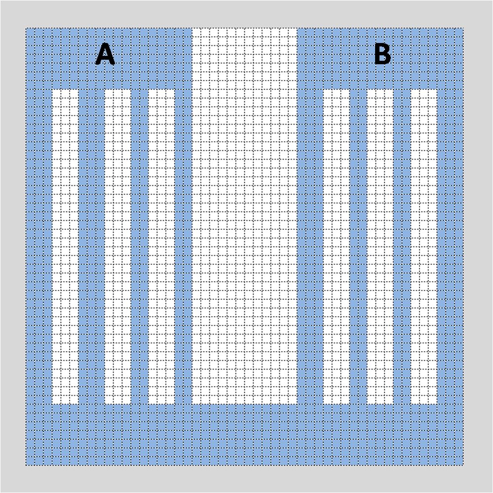
Circuit for heating element

Your advice and explanation will be very helpfull. Thank you.

\$\endgroup\$

2 Answers 2

0
\$\begingroup\$

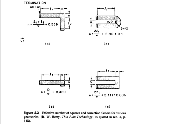
As well as Ignacio's answer on the straight bits, you can consult "Handbook of Electronic Package Design, By Michael Pecht" which has formulas used for correcting for the corner geometry when you use a serpentine (meander) pattern.

enter image description here

\$\endgroup\$
1
\$\begingroup\$
  1. Based on the quotation, if I have 50mm x 50mm & another one is 10mm x 10mm silver ink with same thickness, the ohm will be the same which is 10miliohms. Is it logic?

Yes. The increased width and increased length counter each other, resulting in the same resistance for both.

  1. Another question is, how to measure the resistance if I design a complicated circuit as per attached image?

Fill it with squares, and do the calculations for resistances in parallel and series as normal. You won't get an exact number, but you should be in the ballpark.

\$\endgroup\$
4
  • \$\begingroup\$ Thanks @Ignacio Vazquez-Abrams . Not really understand the answer for no.2. Is it my calculation on this link correct? tinypic.com/r/14vlk61/8 \$\endgroup\$
    – zikri
    Commented Jul 1, 2015 at 2:31
  • \$\begingroup\$ Not "count up the number of small squares", you need to literally fill it with the largest squares possible around the point you want to measure and then do the calculations for those. \$\endgroup\$ Commented Jul 1, 2015 at 2:38
  • \$\begingroup\$ Sorry..I really not good in electrical..Is it mean I fill with squares, so it be like this image --> i60.tinypic.com/2cdtmis.jpg , and then measure the resistance in series for 3 separate part(I circled in orange)? \$\endgroup\$
    – zikri
    Commented Jul 1, 2015 at 7:26
  • \$\begingroup\$ Anyone who can explain details? @Spehro Pefhany \$\endgroup\$
    – zikri
    Commented Jul 2, 2015 at 2:42

Your Answer

By clicking “Post Your Answer”, you agree to our terms of service and acknowledge you have read our privacy policy.

Not the answer you're looking for? Browse other questions tagged or ask your own question.