Say I found an toroid inductor lying around, what is the method of estimating its AC resistance? DC resistance is easy to know, so is its inductance. Is it essential that I have information about the wire?
-
1\$\begingroup\$ An inductor has impedance, not resistance. The effect of the wire resistance is the same as a resistor in series with a perfect inductor. There are many sites that discuss the analysis of an LR circuit. electronics-tutorials.ws/inductor/ac-inductors.html \$\endgroup\$– Mattman944Commented Sep 16, 2022 at 3:54
-
\$\begingroup\$ Are you talking about its reactance? That can be easily calculated from the frequency of the AC and the inductance of the inductor. Or are you talking about the resistance at increased frequency, where you need to consider skin effect and proximity effect? \$\endgroup\$– HearthCommented Sep 16, 2022 at 4:01
6 Answers
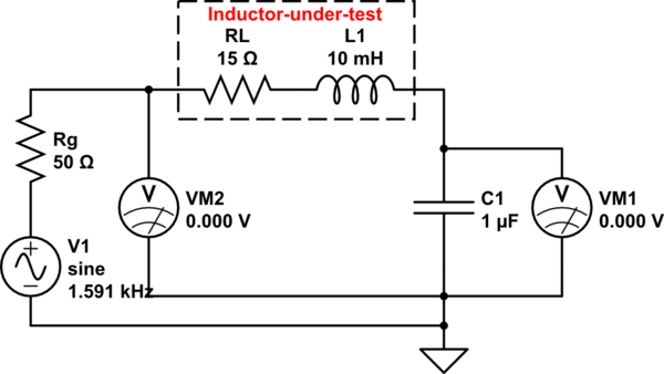
AC resistance measurement might be done with the aid of a good-quality capacitor in series with the inductor. Choose a capacitor value so that resonance with the inductor-under-test occurs at a frequency close to the frequency where you intend to apply the inductor. Since capacitors generally have higher quality (Q) than inductors, the effect of the capacitor's internal resistance might be ignored. But do try to avoid using polarized capacitors.
The measurement proceeds by exciting the series circuit with a function generator at the series-resonant frequency. One must know the generator's internal resistance (often 50 ohms).
One might also use a variac transformer to excite the series circuit, so long as the capacitor (or some series-parallel capacitor combination) has been chosen to resonate with the inductor-under-test at the line frequency (50/60 Hz).
One can monitor the circuit two ways:
- a current monitor connected in series
- a voltage monitor across the inductor OR capacitor. Voltmeter should have high internal resistance.
Current maximizes at resonance. Total series resistance is \$R_G\$ (generator's internal resistance) plus \$R_L\$ (internal resistance of inductor) plus \$R_M\$ (current monitor series resistance).
Voltage across the inductor or voltage across the capacitor maximizes at resonance, and can reach dangerously-high voltages if capacitor + inductor + function generator have low internal resistance.
If one uses a function generator, you might want to monitor two voltages
- function generator output voltage (VM2)
- voltage across the capacitor (VM1)

simulate this circuit – Schematic created using CircuitLab
\$ R_L = R_G \times {{VM2}\over{V1-VM2}}\$ at resonance. \$V1\$ is open-circuit generator voltage
\$ R_L = {{VM2}\over{VM1}} \times {{1}\over{2\pi{f_R}C}}\$ where \$f_R\$ is series-resonant frequency
In the example above, resonance occurs near 1591 Hz. With \$V_G\$ of 1V, VM1=1.542V and VM2=0.23094V
The two-voltmeter method doesn't require knowing the exciting-source internal resistance \$R_G\$.
This method should be limited to amplitudes where the inductor operates linearly. If an oscilloscope is used to measure voltages, rather high test-frequencies can be used, but wire-dressing to the generator should be short.
You need to inject a sinusoidal voltage into your toroidal inductor an get plots (in tabulated data form) of the resulting voltage and current curves across and through the inductor.
From there you use the tabulated data of those curves to calculate the real and reactive power. You can then use that to find the impedance which will be a complex number. The real component of that complex number is the DC+AC resistance lumped together that is dissipating real power inside your inductor.
Then you take the DC resistance that you measured separately and subtract it from the real component of the impedance. That gives you the frequency dependent resistance.
That means you need a signal source, an oscilloscope, and a current probe.
-
\$\begingroup\$ @ DKNguyen okay thanks. So I should have a different AC resistance for different frequency right? I got a variable frequency RLC meter that gives me the impedance for any f I choose. That should be the way to go as to back out the AC resistance? \$\endgroup\$– FlakRCommented Sep 27, 2022 at 1:12
-
\$\begingroup\$ @HYQ If you have an RLC meter you might as well just use that. Subtract the resistance measured when the meter is set to DC (sometimes called DCR) from the resistance measured when the meter is set to some frequency. \$\endgroup\$– DKNguyenCommented Sep 27, 2022 at 1:18
'AC resistance' if you mean the parameter that causes losses that is not solely the DC resistance is quite difficult to measure.
In addition, if parts of it are caused by eddy currents (in the inductor itself, or in nearby conductive paths), it is very frequency dependent.
If it has a ferrite core, the AC resistance depends on the amplitude of the applied signal as this affects inductor saturation and B-H hysteresis.
A practical way is to drive the inductor with a square wave from a DCDC power stage or similar; measure the input current; square wave amplitude, output voltage and current, calculate the inductor losses and assign the 'AC resistance' to the inductor losses.
This requires care and accurate measurements because the losses are relatively small (compared to the lossless power flowing in the inductor), so small errors in the measurements lead to large errors in the result.
Inductors are typically by far the most imperfect of the L-C-R trinity.
The inductance will usually change (sometimes drastically) with the current. If it's air core it will not saturate, but the inductance may change significantly based on what is near it. The DC resistance will change with temperature (and it's sometimes quite significant).
In addition there is distributed capacitance (often quite significant at high frequencies as you approach the self-resonant frequency), there are core losses (which, of course, vary with frequency and temperature), and skin effect.
For some idea of how these parameters can be measured you can refer to this Keysight document, including the section on applying a DC bias to inductors. Ideally you'll have a spare few tens of thousands of dollars to buy the professional equipment. If not, it's possible to rig up tests for specific operating conditions, assuming you have some idea of what those might be.
ac resistance \$R_{ac}\$ can not be measured directly. It depends upon:
- Eddy current losses.
- Hysteresis loss in iron core.
- Radiation losses.
- Skin effect.
These are frequency dependent and increase with frequency.
You can get \$R_{DC}\$ with a meter.
Random inductor so inductance may be unknown. But many meters have Capacitance measuring ability. Use resonance and a measurable capacitor to determine inductance.
Connect a small resistor in series with the inductor, a capacitor and a funcion generator. Measure \$V_R\$ vs \$V_S\$ with a scope. \$V_R\$ will be in phase with ac current, so scope is indirectly measuring I vs \$V_S\$.
Same thing can be done by trying to get the capacitance voltage equal to inductance voltage but effective resistance throws off inductance voltage.
Apply a voltage and vary the frequency until \$V_R\$ is in phase with \$V_S\$. This is resonant frequency. Measure C and use resonant frequency to determine L.
$$f_R = \frac {1}{2 \pi \sqrt {LC}}$$
I'd select another scale capacitor and repeat measurements to verify L calculation.
\$R_{ac}\$ is frequency dependent.
Circuit is function generator and inductor. Adjust function generator to target frequency. Apply a voltage and measure current. Calculate impedance.
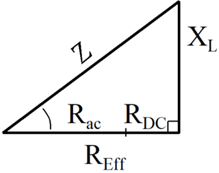
Calculate Inductive Reactance \$X_L\$. Use Pythagoreaus to determine the effective resistance \$R_{Eff}\$ of the inductor.
$$Z = \sqrt {R_{Eff}^2 + X_L^2}$$
Subtract \$R_{DC}\$ and you get \$R_{ac}\$.
I'd also repeat at a lower and higher frequency to understand impact frequency has on ac resistance.
Resistance is a DC characteristic of an inductor (ESR or Equivalent Series Resistance). Inductance is the AC equivalent of resistance).
ESR can be estimated using the length of wire and wire gauge.
Inductance is dependent on lots of things (coil diameter, turns count, turns spacing, core reluctance, core saturation, etc) and weakly dependent on wire diameter.
-
4\$\begingroup\$ Resistance can be frequency-dependent at high enough frequencies; skin effect and proximity effect reduce the wire's effective cross-section at high frequencies. \$\endgroup\$– HearthCommented Sep 16, 2022 at 4:02
-
2\$\begingroup\$ The AC resistance OP is referring to is basically any frequency dependent phenomena that results in power being dissipated. Things such as eddy current losses where even though the loss is resistive, the magnitude of the current being applied to it is dependent on frequency. \$\endgroup\$– DKNguyenCommented Sep 16, 2022 at 4:10
-
1\$\begingroup\$ What @Hearth said. The fact that resistance (of a wire) doesn't depend on frequency is the "lie to children" that is told in basic electronics courses, even at university. It's part of the modeling of lumped linear circuits theory. Once you begin studying EM theory applied to relatively low frequencies (at high frequencies you dump that model altogether and begin using Maxwell's equations more or less directly) you discover "nice" things like skin and proximity effects. \$\endgroup\$ Commented Sep 16, 2022 at 6:14
-
\$\begingroup\$ FYI, skin and proximity effects also affect HV overhead power lines working at just 50/60Hz, with their big-cross-section cables. These latter are made with aluminium wires wrapped around a steel cable core and not pure copper, since the steel core is not really involved in current conduction and the higher losses (with respect to copper) aluminium compensates this by its light weight compared to copper. All in all such a cable ends up being more convenient (both in management and losses) than using pure copper wire (which is enormously expensive, heavy and less robust mechanically). \$\endgroup\$ Commented Sep 16, 2022 at 6:19
-
\$\begingroup\$ @LorenzoDonatisupportUkraine Yes, the frequency where it starts to be significant is a function of wire diameter, and at larger diameters (as used in overhead power lines) the frequency at which skin effect starts to matter goes down. In an inductor like you'd use in everyday electronic devices, the wire is small enough that it takes higher frequencies for this to matter, though. \$\endgroup\$– HearthCommented Sep 16, 2022 at 13:02

