0
\$\begingroup\$

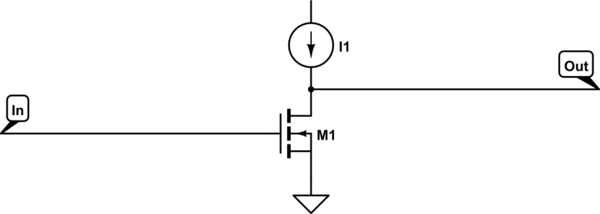
Consider a Common Source NMOS amplifier with current source as a load.

schematic

simulate this circuit – Schematic created using CircuitLab

If the drain current is constant as dictated by the current source, how could Vin change the drain current of the transistor?

EDIT:

If there is a current source load connected to the drain of a CS amplifier, would the current be determined by the current source alone?

\$\endgroup\$
1
  • \$\begingroup\$ In the future you can use the circuit editor to create an image rather than looking for images. You can also simulate the circuit. \$\endgroup\$ Commented Jun 28, 2015 at 15:27

3 Answers 3

1
\$\begingroup\$

In the ideal world, it can't — but the voltage can still change.

In a common-source circuit, the output voltage is a function of the effective resistance of the current source (in parallel with any load resistance). With an ideal source, that resistance is infinite, resulting is just two output states. But in any real circuit, the effective resistance is very high, but finite. This high load resistance creates a high voltage gain for the amplifier stage.

\$\endgroup\$
2
  • \$\begingroup\$ Correct me if I'm wrong. If the current source is ideal, change in input voltage can't change the drain current. If it is a practical source, the change in input would simply change the voltage drop across the current source. So the output voltage changes with change in input voltage without changing drain current. \$\endgroup\$
    – JGalt
    Commented Jun 28, 2015 at 14:15
  • \$\begingroup\$ Could you please have a look at the edited question? \$\endgroup\$
    – JGalt
    Commented Jun 28, 2015 at 14:31
0
\$\begingroup\$

At DC, the only paths that can divert the CC source are gate leakage and any current through the 'out' connection.

If 'out' is open, then we're left with gate leakage. If you assume that's negligible (which it usually would be) then the drain current cannot change (at DC).

However, if the input voltage is too low (your n-channel source follower situation) for the constant current source, the current will arrive via Vds breakdown of the MOSFET rather than source-follower operation.

Of course there is also significant capacitive coupling between the input and the source, so the drain current will change whenever the input voltage changes, then return to the previous value, the change decaying exponentially. If you apply a sine wave at the input, you'll see something like a sine wave in the current, unless it's driven into breakdown, in which case you'll see something considerably uglier.

\$\endgroup\$
0
\$\begingroup\$

If an ideal current source was connected to the drain of a common source amplifier and nothing else was, i.e. there was no output load then the input voltage could not modify the drain current.

However this scenario quickly breaks down in both ways highlighted above.

The current source is never ideal : however lets assume it does have infinite output impedance. It can still not supply current beyond its own supply rails : Vdd and Gnd.

So what happens when we change the gate voltage? For a gate voltage below threshold, the FET is off (refusing to conduct), Vout = Vdd minus a small drop in the current source, which is saturated, or trying as hard as it can to supply current.

Here an ideal current source would simply raise the voltage until the FET breaks down, in order to pass its current ... actually not a good thing.

As we increase the gate voltage above Vth, the FET starts conducting, until eventually it conducts the rated current : now Vout falls below Vdd. Increase gate voltage a little more and the FET conducts more : Vout quickly falls close to 0 and can fall no more.further. So a tiny increase in Vg produces a very large change in Vout : a current source as a load is a trick to give very high voltage gain (ideally, infinite, like an op-amp. Which is why you'll see this trick used in FET opamps).

In a normal amplifier, there will be negative feedback from output to input, keeping the circuit balanced on that knife edge point between fully on or fully off...

The other way this picture breaks down is in the presence of a load resistance. This acts in parallel with the current source, connected from "OUT" to either Vdd or Gnd. (If it's connected to Gnd, its resistance R should be higher than Vdd/I(currentsource), or it will consume all the current when the FET is off, and limit Vout to I * R).

Now, as the FET turns on, it draws current through the resistor. changing Vout as the FET current changes. Now, given the transconductance and load resistance, you can calculate the finite gain of this circuit.
\$\endgroup\$

Your Answer

By clicking “Post Your Answer”, you agree to our terms of service and acknowledge you have read our privacy policy.

Not the answer you're looking for? Browse other questions tagged or ask your own question.