0
\$\begingroup\$

Would like your help to clear my doubt and confusion for this circuit http://nil.rpc1.org/wordpress/?p=31.

I don't get a sense that how possible the RS232-pin3 TX signal is converted and transmitted out from the IR tx.

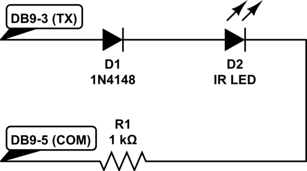
As you look into the photo, the RS232 TX is direct connect to anode of Zener and the cathode is connected -> IR transmitter anode -> resistor ->gnd. That's all.

If saying that, it translates from "-12 -> -0."6 and "+12 -> +3.3v" (1n3138 assuming) then transmit out, how would it be possible?

I am thinking ,the connect orientation should be Zener place from ground with anode and cathode -> IR transmitter -anode? Am i right? With this orientation only the voltage translator able to work.

Can some1 explain further?

\$\endgroup\$

1 Answer 1

1
\$\begingroup\$

First, that 1N4148 is just a diode, not a zener.

Second, just draw out a schematic if you can't follow the circuit:

schematic

simulate this circuit – Schematic created using CircuitLab

Looking at it, strictly speaking the 1N4148 doesn't seem to be necessary, but it does make the leads line up more evenly to terminate to the DB9.

\$\endgroup\$
1
  • \$\begingroup\$ The LD271 IR LED is only rated for 5V reverse bias, so the diode is necessary if RS232 TX goes to -12V. \$\endgroup\$ Commented Sep 14, 2015 at 19:52

Your Answer

By clicking “Post Your Answer”, you agree to our terms of service and acknowledge you have read our privacy policy.

Not the answer you're looking for? Browse other questions tagged or ask your own question.