3
\$\begingroup\$

I have designed a function generator with the intent to provide test signals to a microcontroller or ADC of some other device. However, I may forget that a year down the line and plug it into some circuit on my breadboard. What I'm worried about is damage from short circuits and high current draw. At the moment, there's a buffer OpAmp as the last output stage and the output is bipolar.

First of all, do I need to add an Rs or Zs (impedance match), for example of 50 Ohm? The output can go up to MHz. Does the buffer OpAmp suffice for that?

I have seen the following examples of short-circuit protection/current limiting. I'm not sure which apply to bipolar wave forms; it seems that some were for DC power supplies.

  1. Two NPNs together, but this is for single rail.

  2. enter image description here

Which I first saw here. There were a couple variations given, one with a more complicated current mirror-type addition.

  1. From the same post above in Olin Lathrop's answer, he mentions another config I've seen, which is an OpAmp feeding a MOSFET, which feeds back to its neg. terminal using a sensing resistor. I used something similar in a regulated power supply, but, again, that was DC and I'm not sure it applies here.

  2. foldback supply (Overvoltage protection?)

I would like to avoid a fuse, since I read it's reaction is very slow, plus I don't want to replace it. :)

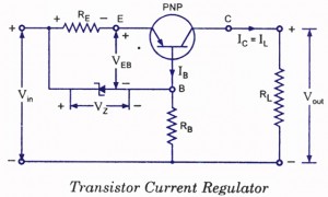
There's a lot of info on this topic and I feel underqualified to decide which is best for me. "Best" in this case is a simple design (like the transistor current regulator) that is robust enough to stop me from frying anything if some knucklehead (me) connects the two leads together. I'm OK with a little attenuation on my signal and a temporarily higher current as long as nothing's damaged. This is just a workbench tool, so the constraints are somewhat liberal. Maybe the buffer OpAmp's output stage can handle this, but I'm not sure.

One last thing: should I add diodes to the rails to protect against voltage spikes? Or would the current limiter also protect against that?

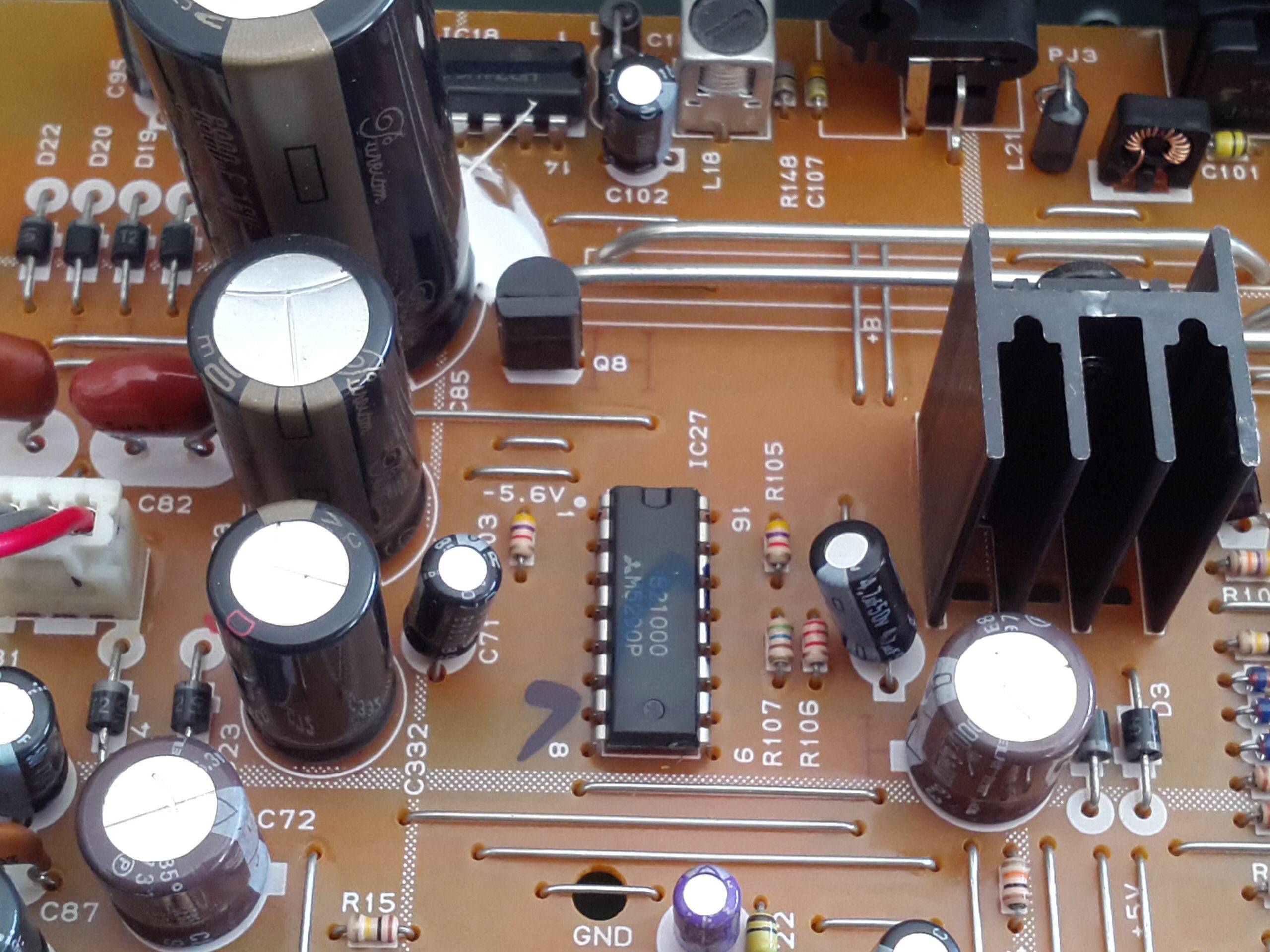
EDIT: The supply I'm using has a voltage regulator with current limiting, which can handle +/- 30mA. I don't know if that changes anything. It's a Mitsubishi M5290P and shown below:

enter image description here

Here's my output stage. OpAmps are STLM358N.

enter image description here

With just the 50Ohm Rs I get no distortion and a current draw of around 1mA.

UPDATE: I simulated the transistor current regulator with multiple values for the elements and it either had sharp edges in pole transitions or completely killed the signal.

\$\endgroup\$
8
  • \$\begingroup\$ What is the maximum frequency of your function generator? \$\endgroup\$
    – The Photon
    Commented Aug 1, 2015 at 15:17
  • \$\begingroup\$ I'm using a uC which has a 32MHz clock, so I think I could get up to around 1MHz, but haven't tested it yet and probably will never use that frequency. \$\endgroup\$
    – MrUser
    Commented Aug 1, 2015 at 15:47
  • \$\begingroup\$ You should post the schematic of your project. At least the part concerning the output stage, with all the relevant parts numbers. Otherwise it is difficult to answer your question in a detailed way. \$\endgroup\$ Commented Aug 1, 2015 at 15:54
  • \$\begingroup\$ @LorenzoDonati Done. See above. \$\endgroup\$
    – MrUser
    Commented Aug 1, 2015 at 16:15
  • 1
    \$\begingroup\$ With the 50 Ohm internal source resistor in place it is unlikely that there will be huge difference in how the output will behave if it is shorted as opposed to connected to a 50 Ohm load. I would not see any need to add short circuit protection, clamp diodes to the power rails might be prudent though. \$\endgroup\$
    – KalleMP
    Commented Aug 2, 2015 at 17:18

2 Answers 2

1
\$\begingroup\$

The LM358 OpAmp is current limited to typically 40mA.

With a +-5V supply you are limited to +3.5V and -5V output excursion.

If you short the output you will source 3.5/50=70mA or sink -5/50=-100mA into the grounded 50Ohm series resistance. This will result in a max of 0.245W (when positive) or 0.5W (when negative) dissipation.

Unless you have a constant -5V output that is shorted you will see an average that is less than 0.5W dissipated, if you remain in the linear portion of the output (+3.5V -3.5V) you will have less than 0.25W into a short. You do not need extra short circuit protection at those supply voltages.

The OpAmp is rated continuous short circuit proof with less than 15V supply.

If you have it calibrated for 2V open circuit you will see 1V across a 50 Ohm load and have a matched source impedance and not be able to approach any device limits.

I would suggest fast diodes connected from the output to the supply rails to prevent external devices from causing device limits to be exceeded.

EDIT: The max current limits calculated cannot be achieved with this particular OpAmp as it lists a short circuit output current of 40mA typical 60mA max and safe for continuous short circuit, it is inherently protected and the current limit protects the output resistor. Higher output currents could be reached with some other types. The max output voltage is listed as the positive supply - 1.5V hence the 3.5V positive limit with a +5V supply, devices that can swing closer to the supply rails are also available and have their uses.

All of the numbers used are available in the data sheet, either in the text, tables or graphs. Note 1 on Table 1 warns about short circuit dissipation limits with supplies over 15V

Calibration at 2V was just my suggestion for the choice of gain components so full-scale digital output would be calculated to give 2V output or 1V into a matched 50 Ohm load, these low voltages would also be self protected as the currents would be even less and within the 30mA supply limits to maintain accurate operation.

I keep forgetting to point out that the possible supply current limits of 30mA would be reached before the resistor dissipation or OpAmp limits. This may cause unexpected behaviour especially if one supply rail were to be reduced more than the other for instance, though with this device this is less likely as it is a tracking dual regulator. It is possible to configure the Mitsubishi M5290P for more than 30mA with external transistors so it is not certain that is will be current limiting at 30mA in this re-purposed power supply circuit.

\$\endgroup\$
1
  • \$\begingroup\$ Thank you a good overview of design parameters/limits. Where in the datasheet did you find that "The OpAmp is rated continuous short circuit proof with less than 15V supply?" And what do you mean calibrate it for 2V open circuit? There's no input offset voltage pin on these packages... \$\endgroup\$
    – MrUser
    Commented Aug 3, 2015 at 10:58
2
\$\begingroup\$

Unless the amount of power a piece of laboratory equipment will ever be called upon to deliver is too large to be dissipated within the equipment itself, there's often no particular reason why such equipment should attempt to drive signals hard enough that it damages itself in the attempt. It's easy to build a current-limiting circuit using linear electronics if one is willing to heat sink it adequately to dissipate power equal to the source voltage times the limit current [or else set the limit current low enough that no heat-sinking is necessary]. Unless someone is trying to make something unusually powerful or unusually compact (by lab-equipment standards) there's no real reason not to include such heat-sinking. If extended operation under high-dissipation conditions is not expected, the heat sink may only need to be good enough to ensure that a thermal-cutout sensor will trip before other devices on the heat sink are damaged.

It may be also helpful when designing a logic-controlled function generator to have a circuit that can report whether the actual output waveform is within a certain tolerance of the specified waveform. For this to be useful, it may be necessary to replace "square waves" with configurable-slope "trapezoid waves". If one attempts to use crudely-current-limited outputs to drive a somewhat-capacitive load with a sharp-edged square wave, the edges are likely to end up with weird and uneven slopes. Using edges with programmed slopes will likely yield much better results.

For digital function-generator purposes, I would suggest having at absolute minimum a 10:1 ratio between the sample rate and the desired output frequency; a 100:1 ratio would be better. If you use a high enough ratio, even very crude filtering circuitry on the output of the DAC will be sufficient to yield good results. It might be possible to get good results using a lower sample rate using better filter circuitry, but if your goal is to generate waveforms up to 1MHz, using a 50MHz clock might be easier than designing filtering sufficient to yield acceptable results with a 10MHz clock.

Although most DAC-based waveform-generation approaches use at least a second-order anti-aliasing filter to "smooth" the output waveform, I would suggest taking the opposite approach. Use an op amp to build a first-order low-pass filter with a very low cut-off frequency but very high gain (basically an integrator) and either use software to compute the inverse function of that filter (pretty straightforward) or, or use a "pure" integrator (zero cutoff frequency) and an ADC and software-based feedback. You'll need to make sure that you update the waveform fed to the DAC precisely at the inflection points, but you should be able to get much cleaner output waveforms than using more typical approaches.

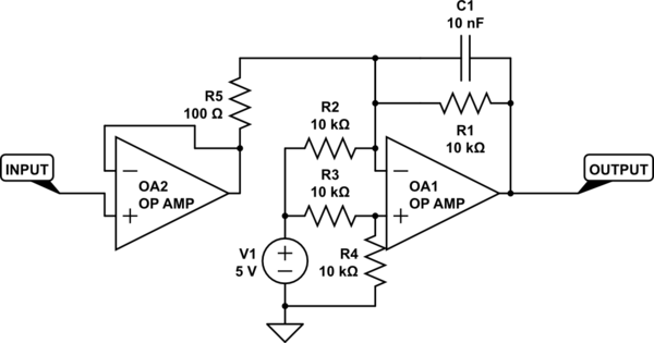
Using either approach, the goal would be to have software determine for each sample what value it should output to the DAC to make the output waveform ramp toward the voltage it's supposed to have at the time of the next sample. Consider the following integrator circuit:

schematic

simulate this circuit – Schematic created using CircuitLab

If at some moment in time the output is at voltage X, and one wishes to be at voltage Y one microsecond later, one should feed the circuit an input of (2.5+(Y-X)+(X+Y)/200) volts which will cause the output to ramp smoothly to that new voltage. This calculation isn't quite exact, but it should turn out pretty close. Accuracy/resolution at low frequencies could be enhanced by increasing C1 or R5. The "/200" factor in the above equation is the twice the ratio of R1 to R5 [doubled because the formula is taking the average of X and Y], so changing C1 would not affect that ratio but changing R1 would.

\$\endgroup\$
5
  • \$\begingroup\$ Thanks for the detailed response, but about the heat-sinking: I've added a photo above that shows the little heat-sinking provided in the power supply. The heat-sinked part is a PNP, and the whole power supply is from an old CD player that I dismantled, so the housing is giant with lots of empty space. Is this enough, or do you mean that I should somehow heat-sink my output stage, or just the curr. lim circuit if added? Should I add the CL circuit to the OpAmp power supplies perhaps? \$\endgroup\$
    – MrUser
    Commented Aug 2, 2015 at 12:11
  • \$\begingroup\$ Also, for clarification: I don't want to purposefully deliver large amounts of power. I'm mostly worried about damage due to shorting the leads, from voltage spikes, or from accidentally delivering too much power. \$\endgroup\$
    – MrUser
    Commented Aug 2, 2015 at 12:14
  • 1
    \$\begingroup\$ @MrUser: If you design your device to only output e.g. 10mA max (for example), and the supply rails are +/-10 volts, then a simple current limiter circuit would dissipate at most 0.1W [more or less]. If you want to be able to output up to 100mA and your supply voltages are +/- 12 volts, the current limiter may have to dissipate 1.2W. How much heat sinking you need will depend upon where you set the current limit and what the supply voltage is. \$\endgroup\$
    – supercat
    Commented Aug 2, 2015 at 19:51
  • \$\begingroup\$ Thanks for the advice. As KalleMP suggested, I probably won't need the heat-sinking in this project, but it's a good reference for the future. I'll also consider the output waveform reference in my uC design. By "sample rate", you meant in sampling the output waveform, right? \$\endgroup\$
    – MrUser
    Commented Aug 3, 2015 at 11:01
  • \$\begingroup\$ @MrUser: I just added a suggestion for an integrator output stage which should improve the usefulness of your device with common function-generator output waves since it will smooth the waveforms while leaving them much more linear than they would be with a conventional anti-aliasing filter. \$\endgroup\$
    – supercat
    Commented Aug 3, 2015 at 16:58

Your Answer

By clicking “Post Your Answer”, you agree to our terms of service and acknowledge you have read our privacy policy.

Not the answer you're looking for? Browse other questions tagged or ask your own question.