4
\$\begingroup\$

I'm trying to determine the most effective layout for a 2.4GHz chip antenna on my PCB. I';ve read through a few application notes and Datasheets but none really clarify which antenna setup is most efficient or will allow the best range.

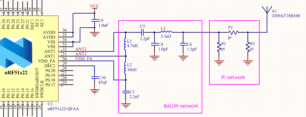
Right now I have looked at two options, but I'm no closer to knowing which might be best. I'm using a discrete Balun network and a pi-network for later tuning.

The two options I'm toying with right now are the horizontal orientation routing: enter image description here
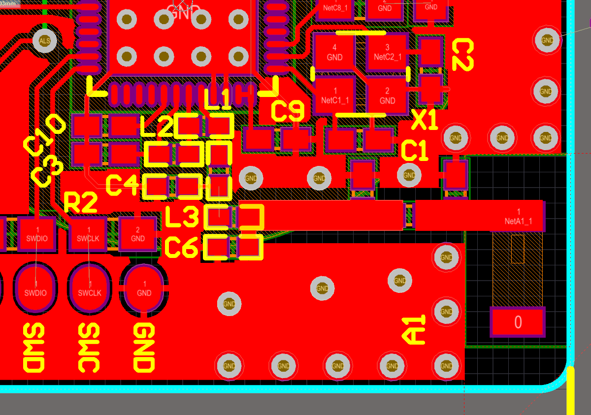
Or the Horizontal routing, diagonal antenna: enter image description here
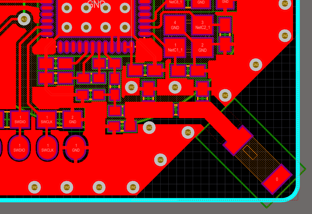
So which one would give me the best range?

I'm also completely uncertain if I've set up the feed-line correctly, so any tips or advice on setting that up correctly would be greatly appreciated too!

Antenna I'm using: http://www.johansontechnology.com/datasheets/antennas/2450AT18B100.pdf

Schematic of set-up: enter image description here

\$\endgroup\$
4
  • \$\begingroup\$ In option A, are you sure you have enough recommended side clearance? It doesn't look like it looking at page 2 of the datasheet. \$\endgroup\$ Commented Sep 15, 2015 at 16:40
  • \$\begingroup\$ Why have you used a pi network instead of the recommended T network? \$\endgroup\$
    – Andy aka
    Commented Sep 15, 2015 at 16:54
  • \$\begingroup\$ I vote for option B, the antenna is a lot better off than in A, being so far away from the ground. You'll still need to tune it by adjusting the Pi network components. \$\endgroup\$
    – tomnexus
    Commented Sep 15, 2015 at 17:28
  • \$\begingroup\$ I definitely don't have the recommended side clearance. I threw that together as an example of orientation. @Andyaka: I used a Pi network becuase that's what Nordic recommend for antenna design. Is there any particular advantage to a T network? If the non-diagonal antenna had the same distance from ground, would it have the same characteristics, or does having one less free side reduce it's capability? \$\endgroup\$
    – Sensors
    Commented Sep 16, 2015 at 10:03

1 Answer 1

2
\$\begingroup\$

I think the second layout is much closer to the design guideline given by the datasheet. Chip antennas are very sensitive for RF ground. So it is important to follow manufactures design guidelines. Also the direction of the radiation varies according to the ground clearance. The second image has a better ground plane clearance than the first.

Please see the link below for more information.

http://info.lsr.com/LSR-Wireless-RF-Design-blog/bid/251039/Antenna-Design-Chip-Antenna-Implementation

It is important to make the length of the trace connecting from the matching circuit to the antenna as short as possible because that could add some inductance as well. Hence a shift in S11.

If you intended to increase the length, I think it is better to calculate the transmission line width over a ground plane. I think it will be good to keep your PI matching pad resistors closer together as well.

As recommended by the datasheet, antenna feed should be a 50 ohm line. You should calculate the width of the transmission line considering as a coplanar transmission line.

Hope this information was helpful for you.

\$\endgroup\$

Your Answer

By clicking “Post Your Answer”, you agree to our terms of service and acknowledge you have read our privacy policy.

Not the answer you're looking for? Browse other questions tagged or ask your own question.