0
\$\begingroup\$

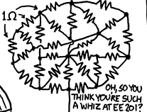
Of course, one way to do it is to split it into series and parallel circuits and apply Kirchhoff's law, but that seems inefficient. Is there a method by which a circuit nest can be solved (finding the voltage and current at each resistor) efficiently (suitable for a computer simulation, perhaps)? (Of course, any approach would be based on Kirchoff's laws, but they can be rearranged to be more efficient for this task.) I am thinking it would involve finding relative voltages at every node, instead of voltage differences at each resistor.

What should I do?

\$\endgroup\$
5
  • \$\begingroup\$ I think you're looking for "nodal analysis". \$\endgroup\$
    – Roger C.
    Commented Oct 30, 2015 at 14:54
  • 3
    \$\begingroup\$ I only see 1 wire in... \$\endgroup\$
    – Tyler
    Commented Oct 30, 2015 at 14:55
  • 2
    \$\begingroup\$ Isn't this form an xkcd comic? Their license requires attribution xkcd.com/license.html \$\endgroup\$
    – Gorloth
    Commented Oct 30, 2015 at 15:12
  • 1
    \$\begingroup\$ @Gorloth: You are thinking of xkcd.com/356 ? \$\endgroup\$
    – PlasmaHH
    Commented Oct 30, 2015 at 15:22
  • \$\begingroup\$ @Gorloth: Hm, it looks like it is a crop from xkcd.com/730 \$\endgroup\$
    – PlasmaHH
    Commented Oct 30, 2015 at 15:29

3 Answers 3

1
\$\begingroup\$

Well in the particular diagram you have shown there appears only one wire coming in. So there will be no current flow in any of the resistors and all the nodes will be at the same voltage.

Edit: looking at the full nonsense circuit on XKCD there is a wire coming into the top of the subcircuit you pictured which you cropped off. If you connected a voltage source to the top and bottom of the circuit you could solve it by the means below.

But in general you can solve a circuit with lots of resistors by the following procedure.

  1. Choose one node to be your 0V reference.
  2. Assign a variable for the voltage of each node other than the reference node.
  3. Assign a variable and direction for the current through each component (including your voltage source). Don't worry if the direction you assign is backwards, that just means you will get a negative answer for it's value.
  4. Write and equation for each node setting the current into the node equal to the current out of the node.
  5. Write an equation for each component (including your voltage source). The voltage source equation will relate the voltages on two nodes directly. The resistor equations will relate the voltages on two nodes to the current through the resistor.
  6. Solve (or get a computer to solve for you) the resulting simultanious equations.
\$\endgroup\$
2
  • 1
    \$\begingroup\$ See the full circuit at xkcd.com/730 cough \$\endgroup\$
    – PlasmaHH
    Commented Oct 30, 2015 at 15:29
  • 1
    \$\begingroup\$ Clearly that "full circuit" makes no sense and cannot reasonablly be solved.... Still i'll update my post. \$\endgroup\$ Commented Oct 30, 2015 at 15:37
0
\$\begingroup\$

Well you didn't give any other information, so from that perspective I can't help. What I can tell you though is that those resistors seem to all be in parallel, and if they are, voltage would be constant throughout the whole circuit. My advice would be to clean it up from that circular/triangular mesh mess, simplify to an equivalent resistance to find the initial current into the circuit, then keep doing calculations as you re-expand backwards.

\$\endgroup\$
2
  • \$\begingroup\$ The resistors in the figure are not in parallel, and not in series. \$\endgroup\$
    – Roger C.
    Commented Oct 30, 2015 at 15:01
  • \$\begingroup\$ Taking a closer look at it, I realize you're right. This is an interesting problem in that case. I find the taunt at the bottom right quite funny though, maybe it's the professor's (if this is for school) attempt to mess with the students haha. \$\endgroup\$
    – kgEE19
    Commented Oct 30, 2015 at 15:12
0
\$\begingroup\$

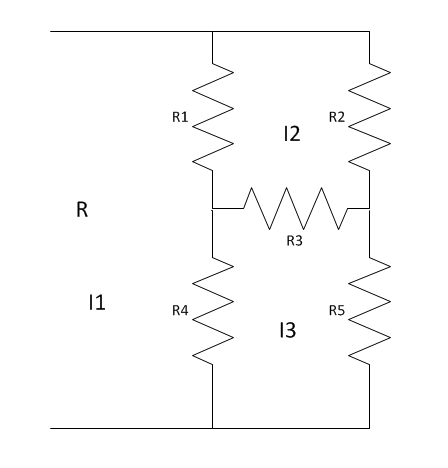
There may be symmetries in resistor nests that you can use to simplify things considerably. Here's an example circuit. If R1=R2 and R4=R5, you have the same voltage at each side of R3, so VR3=0, therefore current (I2-I3)=0 and you can ignore R3. This simplifies the calculation. Resistor network
I got nerd sniped and distracted here (see another XKCD on that!). Mathics is opensource code that let me solve the Kirkoff law's linear equations symbolically. Maybe the closed form equation will entertain someone.

Resistor network equation

It's been a while since I did circuit analysis, and a lot of the professional tools are expensive. There's a free opensource tool called Qucs, which lets you draw your resistor nest circuit diagram, and you can calculate the total resistance by adding a voltage source to the circuit and finding the current, R=V/I.

Last but not least, the XKCD nest is small enough to fit on any breadboard with a dollar's worth of 1K resistors, and you can measure it.

\$\endgroup\$

Your Answer

By clicking “Post Your Answer”, you agree to our terms of service and acknowledge you have read our privacy policy.

Not the answer you're looking for? Browse other questions tagged or ask your own question.