Happily, it looks like the controller operates entirely after the ACDC transformer, so I'll probably just replace it with a DCDC converter and not have to deal with making my own controller.
I took the thing apart anyway and have some analysis and photos to share in case anybody is interested in this in the future.
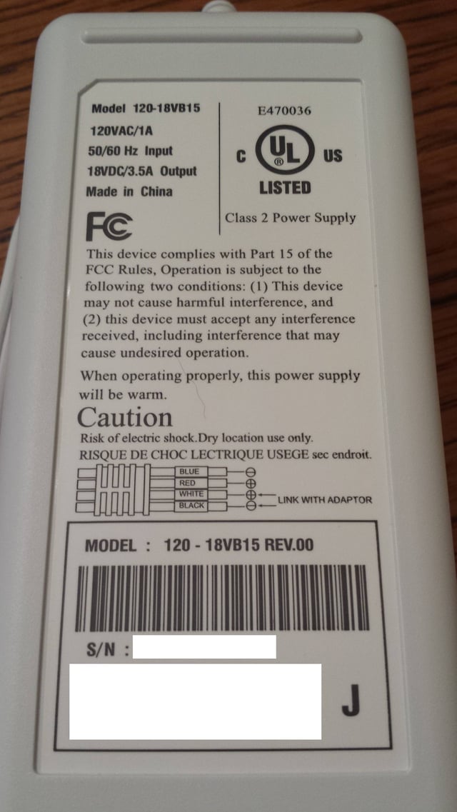
Power supply is rated for 18VDC output at 3.5A (63W)
Blanket element is just 2 leads. Measures at 4.6-4.7 ohms at 77 degrees F.
Measures 4.0-4.2 ohms after the whole blanket was in the freezer for an hour. After running for 15 minutes or so on high (until the blanket felt warm while folded in 4 layers), it measures 5.1-5.2 ohms, so it does look like the resistance is significantly dependent on temperature.
Element resistance seems a little low; as measured (including other resistances in the supply path) it would dissipate 68+ watts, but the supply is only rated for 63. It may be my cheap RadioShack meter having a static offset (overcompensating for resistance internal to the meter?) since the measurements are repeatable and steady. On the other hand, the power should be a little lower (higher element resistance) when it heats up during operation, so the manufacturer may have decided a slight excess while cold was close enough.
On the 120V side, the unit consumed 76 watts (as measured by a Kill-A-Watt meter) when I first plugged it in, but is consuming 65 after warming up. This doesn't say much about power use when cold, as the transformer efficiency is unknown, but does show that it draws under or very close to the rated power when warm.
Lets take a look inside the controller
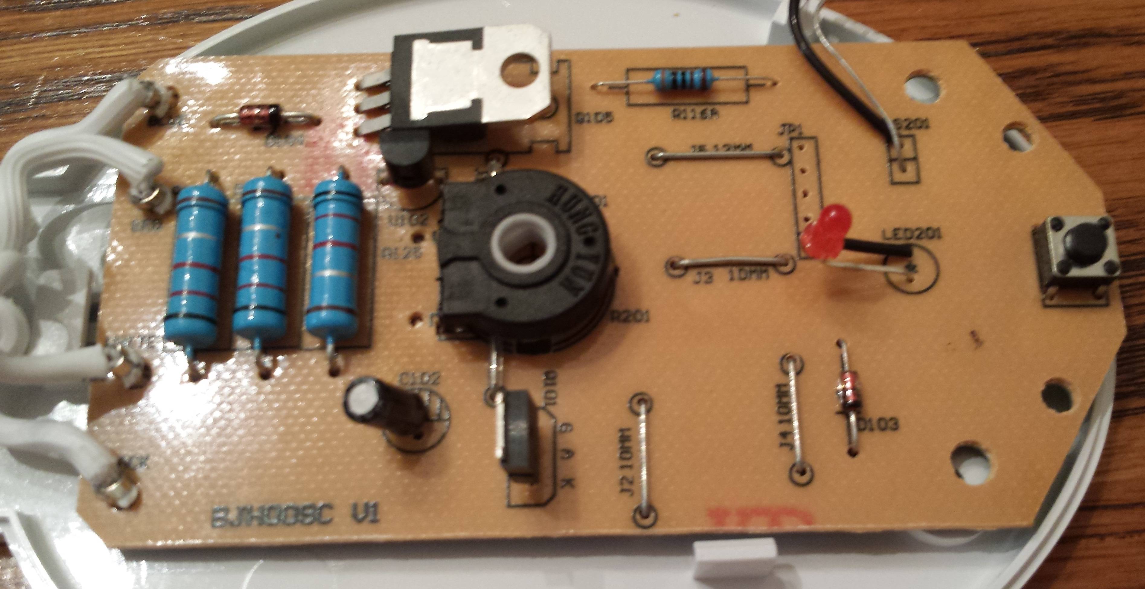
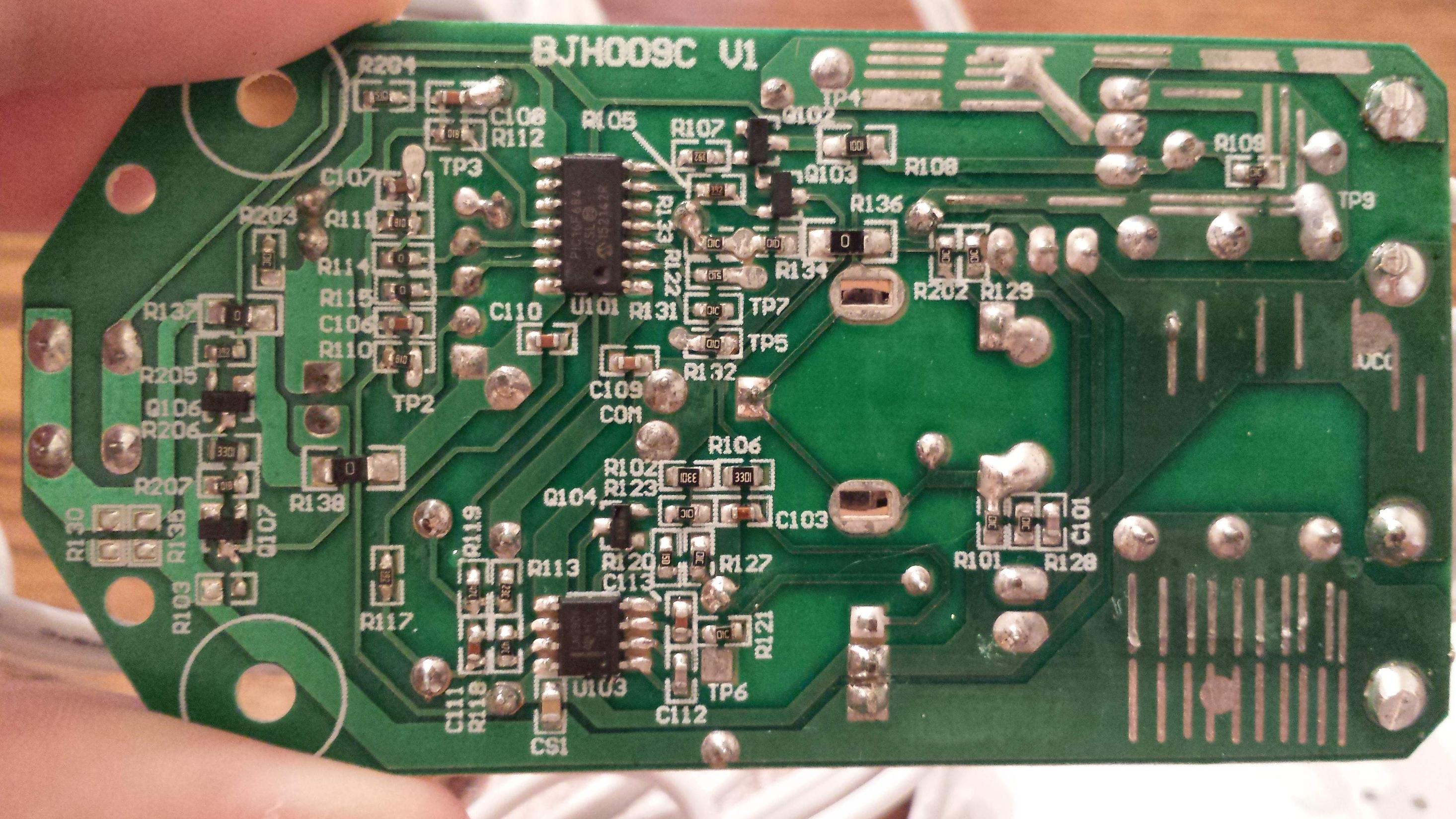
The design uses a common positive rail (direct connection to blanket's positive terminal) - control operates on the negative rail.
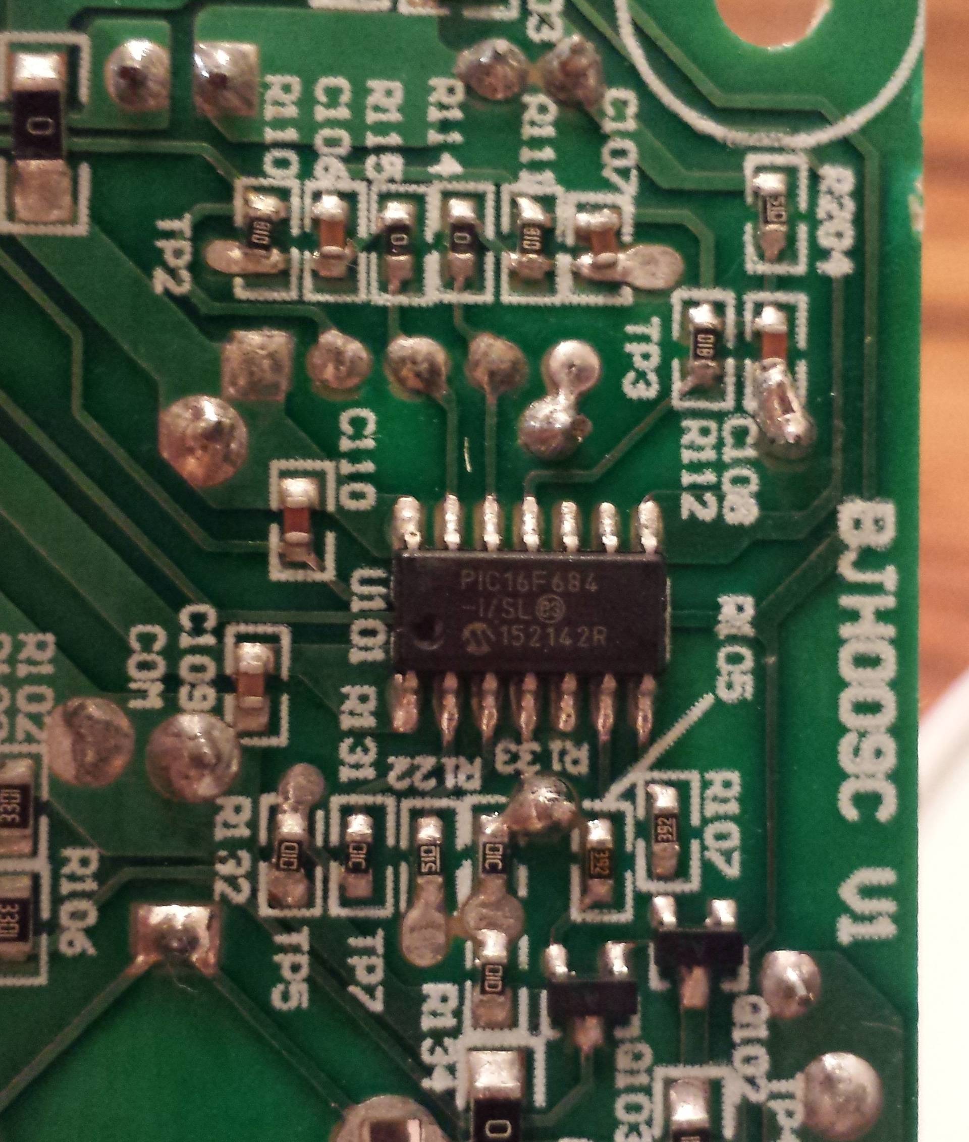
Using an 8-bit PIC microcontroller (PIC16F684)
Element is directly connected to positive rail
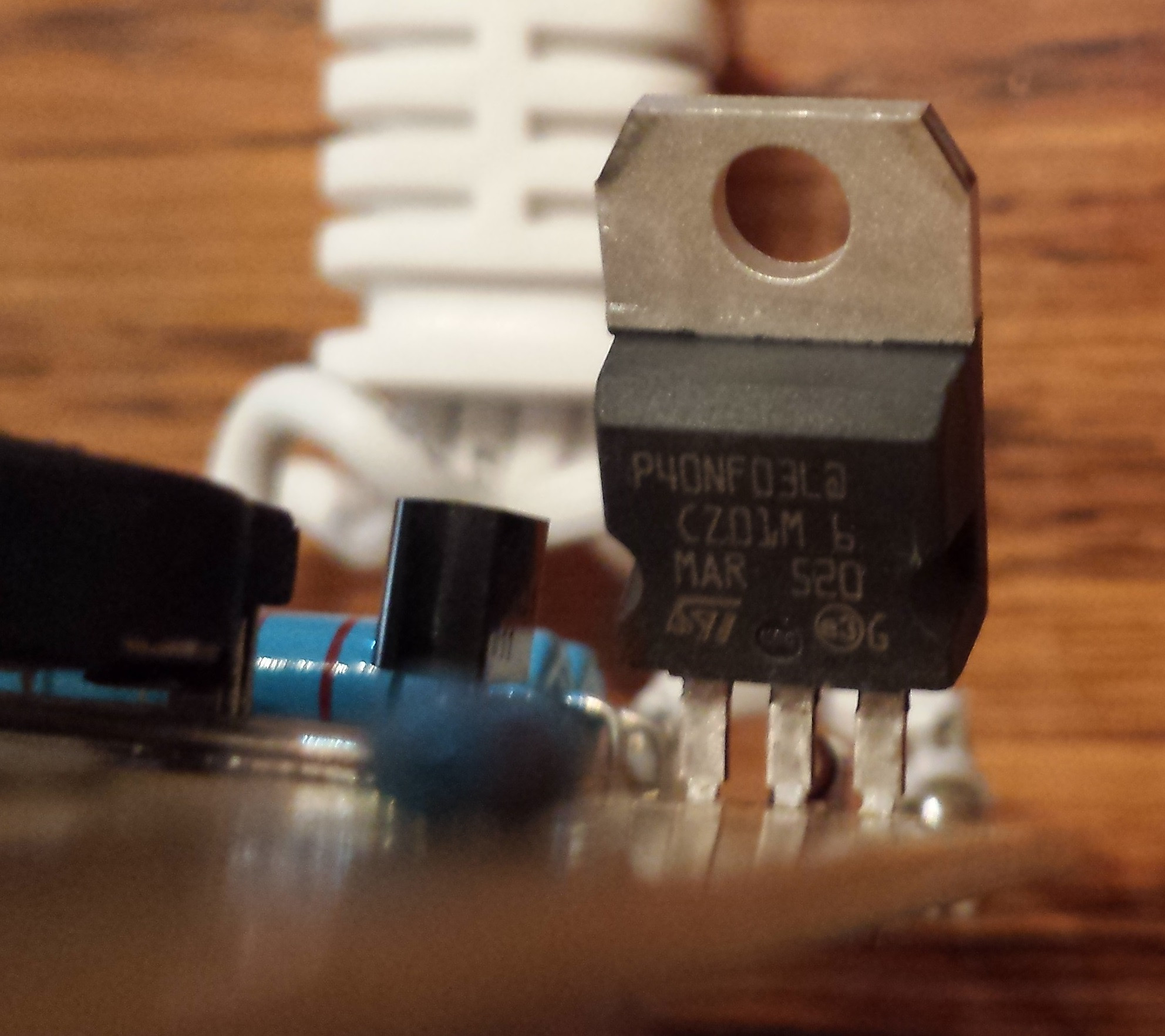
A mosfet switches on the negative output from right after an inline shunt from negative supply. More or less controlled directly from one the PIC's output pins.
P40NF03L - 40A 30V N-channel MOSFET. 0.020 ohm when operating
The shunt (the 3 big 0.22 ohm +-1% resistors in parallel on the bare side of the board) will dissipate 0.3W each at max rated amperage. They're 2W resistors, I guess they didn't want them to get too hot
LM2904 Op amp (chip on the left in this photo) looks like it is used at least for voltage sensing (and therefore current sensing) after the shunt.
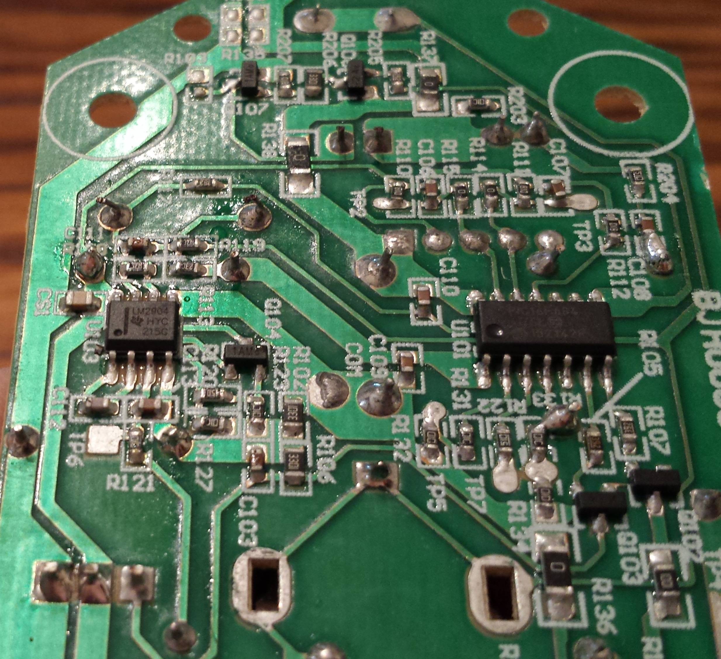
Current sensing is almost surely used for safety reasons, although this is probably how they do temperature sensing as well.
TS12 - SCR from supply positive to negative, appears to be a crowbar, but there is no inline fuse.
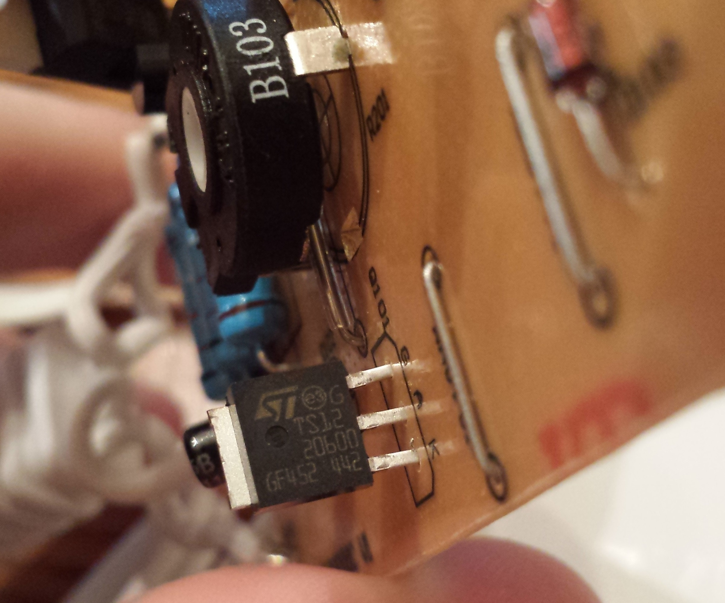
Probably relying on the power supply or the thin part of trace between the main positive rail and the SCR... the trace burning would only protect part of the circuit though. I'll have to ensure I use a fuse (4A?) inline with my DCDC converter.
This looks like a light sensor (photoresistor)... why?
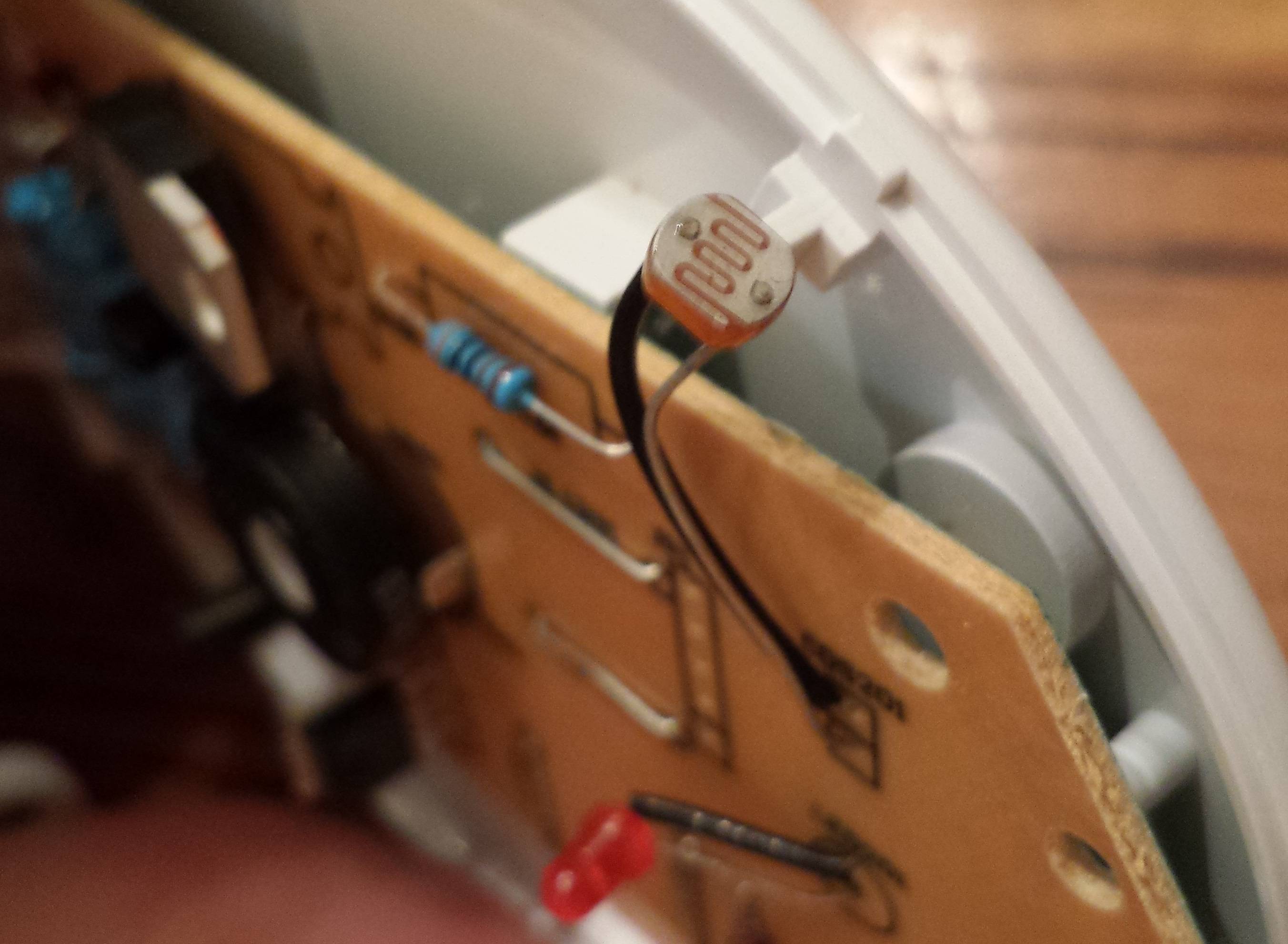
There is a little opening cut in the controller's shell for it to see the outside world. Upon further testing, it immediately and obviously controls the LED intensity that shines through the dial's display to show the power setting. The dynamic range isn't that great (lowest setting is maybe 25% as bright as the highest), and I'm floored that they bothered to put this feature into such a simple product.
Sorry for the mediocre photos, they were taken with a cell phone.


