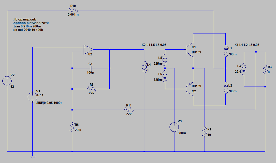
I have been modeling this circuit in LTSpice and it has a tendency to oscillate. The transistors are chattering on and off resulting and a square wave output at ~8 kHz depending but the precise frequency depends on the inductance of the various transformer coils.
What is the source of oscillation in a circuit like this?
I want to understand where the coupling is and not just how to "fix" it.
UPDATE 1:
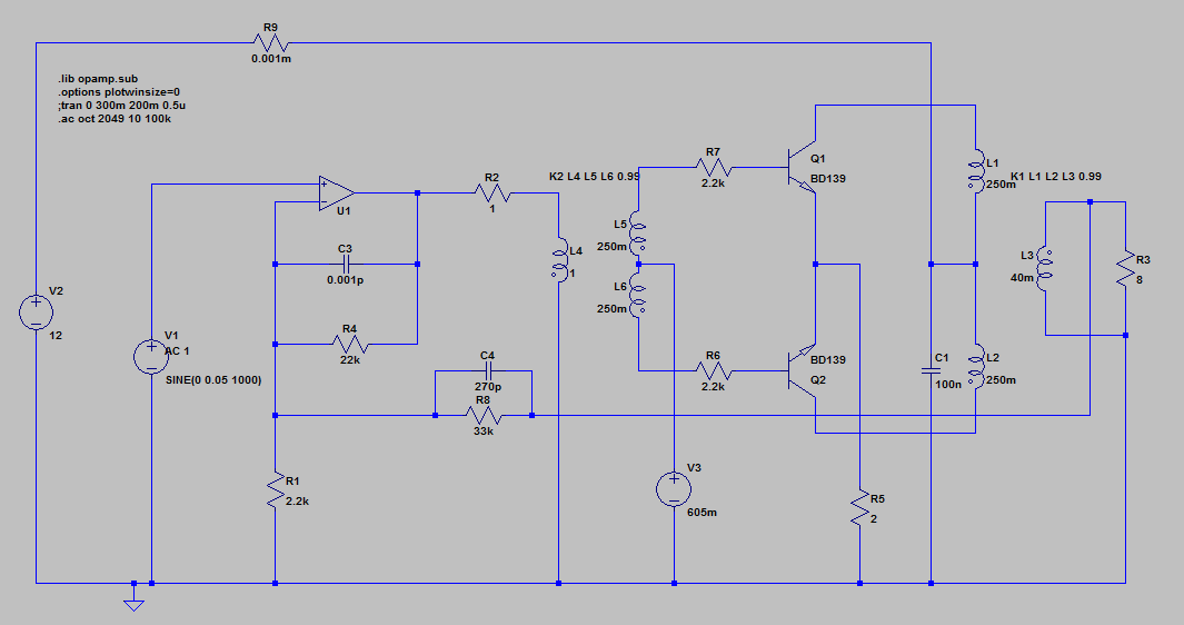
This circuit simulates very well:
In general I think the problem was just impedance mismatching. So adding series resistance with the transistor bases helped. But what I think was more important was the inductance of the output transformer was too high. If I use a ratio like Hammond 106T which is 100R : 8R and pick low inductance values, it behaved much better. So basically it was not loading the transistors enough. As soon as the transistors started to turn on, they would just stall because they couldn't pull current.
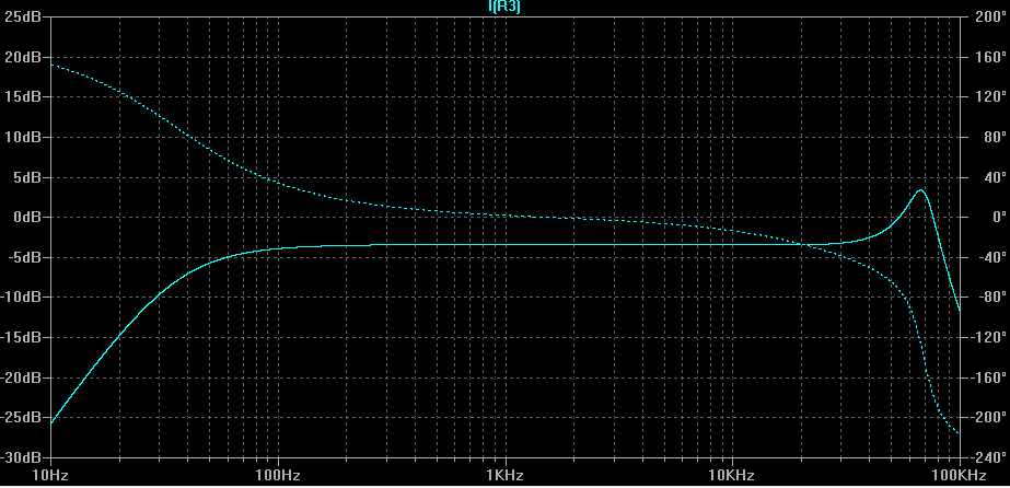
The simulation runs pretty quick and the FFT is flat:
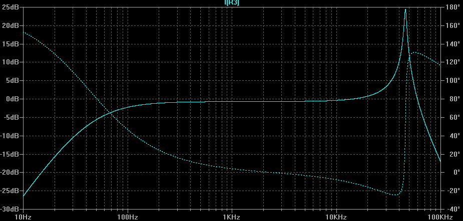
The feedback capacitor also helps to significantly reduce the peak at 48kHz which is where the oscillation actually was:
So the above shows the FFT without feedback. You can see from the first FFT that the feedback significantly tightens the response.
UPDATE 2:
It seems the biggest factor of all in this simulation is leakage inductance which is defined by the transformer coupling factor. I started with 0.98 and then 0.99 and changing this to 1 often completely eliminates oscillations.
The question is - what is the typical leakage inductance of an audio transformer like the interstage and transistor output transformers shown (eg Hammond 106H / 106T)? Is it ok to assume a coupling of 1? Or is 0.99 more realistic. Believe it or not the difference between 0.99 and 0.999 is significant to my simulation. So I need to figure out what this coupling constant would be in practice.


