11
\$\begingroup\$

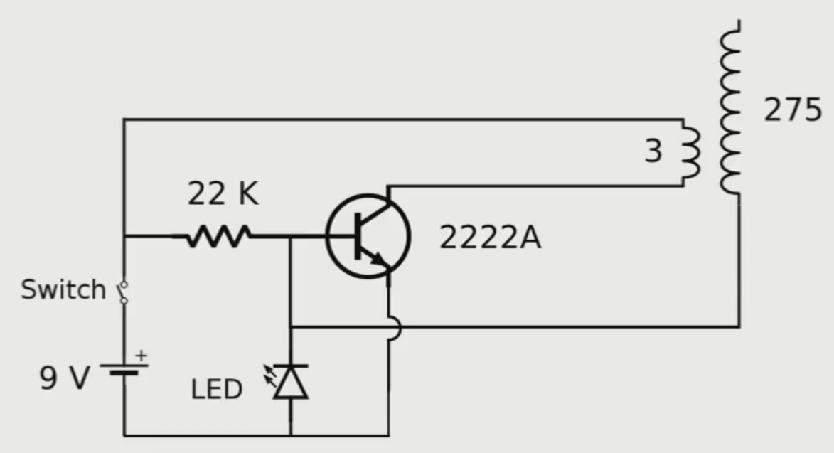
I build this circuit and it works but I have two problems. The major problem is that the transistor becomes very hot quickly. I burnt my transistor due to excessive heat. How can I get rid of the very high temperature of the transistor.

The second problem is that the circuit does not provide enough range. When I approach a florescent lamp, It does not light up. I brought a wire and modified its shape to be round (a circle). It looks like a coil that have one turn. I connected the high voltage terminal to one of the coil's terminals. The other terminal of the coil is not connected (open circuit). When I put the florescent lamp inside the coil it lights up. This is a very small range. I need a good range, something like 5 or 10 cm.
I need to know how to achieve a good wireless range? and What controls the range? Is it supply voltage, the base resistor or something else?

My supply voltage was 10 volts because I don't have a battery of 9 volts. The number of turns of the coil is 300 instead of 275.

Thank you,

enter image description here

\$\endgroup\$
2
  • 1
    \$\begingroup\$ Have you tried finding the current through the coil? \$\endgroup\$
    – Voltage Spike
    Commented Feb 2, 2016 at 20:56
  • \$\begingroup\$ try TIP31C, Replace 22k resistor with 50k. replace led with uf4007 diodes 2 in series. 4 primary turns and 450 secondary. with 10v, 1.5 amp powersupply. \$\endgroup\$
    – user108732
    Commented May 1, 2016 at 13:30

5 Answers 5

6
\$\begingroup\$

Have you tried finding the current through the coil? Find the current through the coil. You can either simulate it with a spice package or place a meter between the coil and transistor. Once you know the current use the equations located in this online textbook in chapter 11 Inductance and Magnetic energy (Yeah it requires math).

Then find the magnetic field through the coil (you'll need to know the area of the coil and the turns.) Then calculate what kind of energy you need at the input coil. I'll give you a hint as to what you'll find. Your coil is generating a magnetic field at a certain frequency, keep in mind the magnetic field is going to 'attenuate' by the the inverse cube of the distance (magnetic field=1/(distance^3)). Meaning if you had 1 unit of magnetic field at 1cm, at 2cm you will have 1/8th of the field, at 3cm you will have 1/27th and so on. By the time you get to 10cm you will have 1/1000 of your original field so you will need ~1000x the current or you will need to redesign your coil.

This is also why there will forever be companies that promise wireless power but you never see any products beyond the charging pads. The lightbulb demonstrations use phenomenal amounts of power even with a directed antenna(coil). The best one I've seen is this one Wireless power transmission. You can changed the antenna/coil however and it can help. Look up Helmholtz coil if you think that might work for your application. If you want you can parallel several BJT's if you want them to get less hot.

\$\endgroup\$
4
\$\begingroup\$

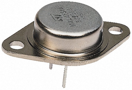
Ideally you would use something more efficient (and necessarily more complex) than a rudimentary slayer exciter, but to easily improve the current circuit you need just a proper power transistor that you mount to a heatsink.
The 2n2222a comes in a TO-92 plastic package, can dissipate a pathetic 625 mW of heat and is only rated for a current of 800 mA.

You want something much beefier, like a 2n3055, which can dissipate 60 W and is rated for a collector current of 15 A. It is probably also the most easily available power transistor.
2n3055

\$\endgroup\$
3
\$\begingroup\$

A 2N2222A is totally inappropriate in this application. That's a small signal transistor. You need a power transistor. There are many to chose from, but something like a TIP41 is something you can probably find easily.

\$\endgroup\$
2
  • 1
    \$\begingroup\$ Internet schematics seem to favor the TIP31. \$\endgroup\$ Commented Feb 2, 2016 at 23:27
  • \$\begingroup\$ @What: I haven't looked up the TIP31, but many NPN power transistors could work in this role. \$\endgroup\$ Commented Feb 3, 2016 at 11:29
1
\$\begingroup\$

Slayerz... I love em.
4k on the base, 7 Turns on the primary. 1000 turns on secondary.

These are all good transistors, 2N6547 was the best. You MUST have a heat sink or you'll cook the poor things.

2N6547 2SC5387 BUF420AW

Search for those on your favorite Chinese supplier and you'll find them all for <£1 each. I use Aliexpress.

2N3055 was OK, but I cooked 30 in a month so moved to 2N6547 (same package).

Why not parallel some transistors up - Try two Tip42s or two 2n6547?

You could build a multi-primary Slayer. I found that the twin Slayer would pull more amperage but not at the cost of cooking a single transistor, the heat was shared between two circuits/transistors. Nice outputs, strong wireless transmission. :D

  1. Build one good Slayer, get the turns nicely balanced with the resistance to base. (use a variable resistor to tune - I used a decent wattage 10k pot).

  2. Replicate the slayer circuit again:

    • you'll need another primary with exactly the same amount of turns.
    • use the same resistance
    • same diodes or LED (if using an LED)
  3. Wrap another primary to the secondary coil

    You now have two identical primaries wrapped around the same secondary. One Slayer circuit is already connected. Time to connect the second circuit.

  4. Connect the primary to the new circuit in the same way as you did with the first.

  5. Next you need to common up the two secondary connections from each circuit to the coil. Make a Y lead so both circuits have the same secondary connection.

  6. Common up the power connections so you have one power supply connecting to both circuits.

  7. Switch on... you should find it's twice as powerful :D

I've made up to four multi-primaries in this way. I made a very powerful Slayer that lights a 60 watt incandescent at 5 foot (coil to coil) using 50v from a bench supply. My bench supply was trashed by my Slayers. Bad earthing on my part.

  • Try adding an earth ground to the negative connection, you could find more power.
  • Try lots of different LEDs if you're experimenting instead IN4xxx Diodes, different colors/types will change your output. :D
  • Try different size toploads, make them by covering items with foil or coffee tins, any old tins - varying sizes, try stacking them up.
  • I was using an old metal bowl for toploads.

You can switch between NPN and PNP. Just swap the power connection around and you're good to go.

Have fun! Cheers, Deeds

There's a stack of Slayer videos on my YT channel showing wireless transmission - search "Deeds Slayer Exciter" and you'll find them. I'm not touting, I just like sharing the knowledge.

\$\endgroup\$
0
0
\$\begingroup\$

The "range" depends on the stored energy in the secondary, that depends on the input power and in the Q of the secondary circuit. To increase the input power you can decrease the number of primary turns or increase the input voltage, but this will heat the transistor. Better to increase the secondary Q, by using more turns. The resistor serves only for startup. You can disconnect it when the circuit is working without any change. The value is not critical. Certainly a potentiometer is not necessary. The LED can be replaced by a single fast diode. No need for two, but the LED shows that the circuit is working. Transistors as the 2N3055, and even the TIP31, are too slow. They may work with large coils with many turns, operating below 1 MHZ. In any way use a heat sink. A possible idea is to use more than one primary circuit.

\$\endgroup\$

Your Answer

By clicking “Post Your Answer”, you agree to our terms of service and acknowledge you have read our privacy policy.

Not the answer you're looking for? Browse other questions tagged or ask your own question.