0
\$\begingroup\$

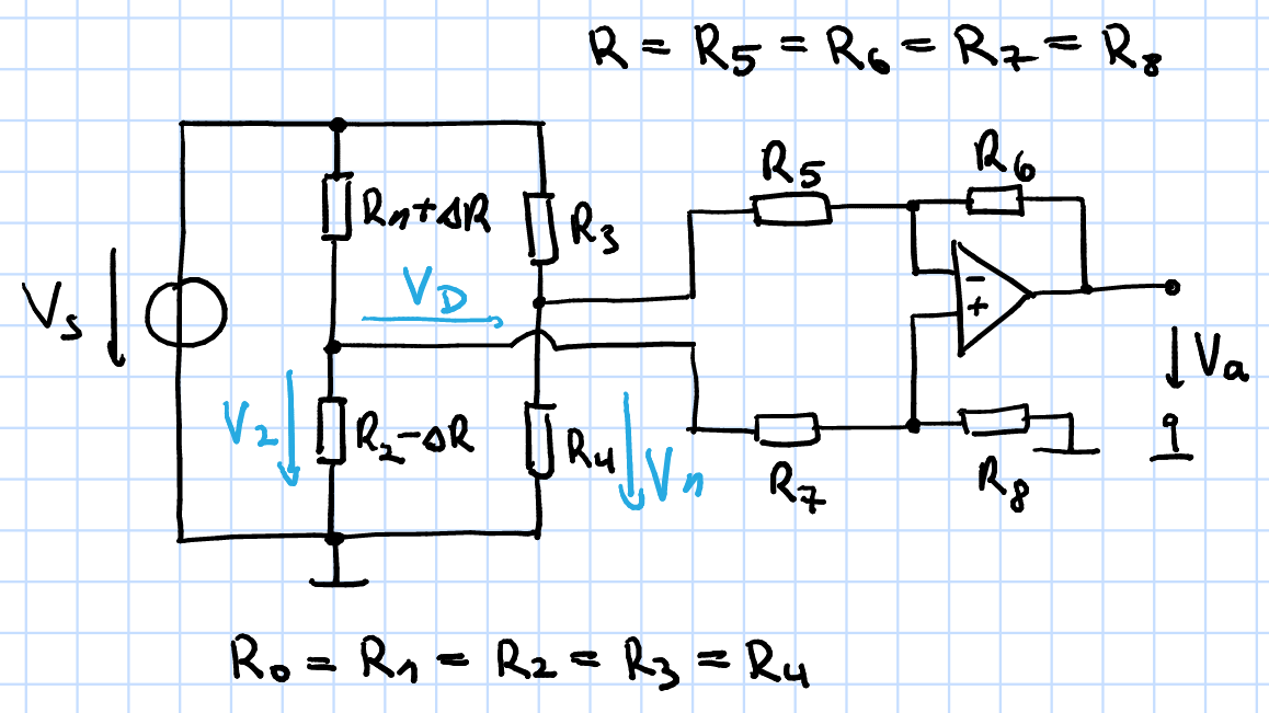
I am currently struggeling with solving the following problem: The circuit below shows a bridge circuit, where the differential voltage between the branches is measured by a differential amplifier. I need to know the relative systematic error caused by using the amplifier circuit.

Given values: $$ R_0=100\Omega \\ \Delta R=1\Omega \\ R=1k\Omega $$

Well, my approach to solve this was to first analyze the bridge circuit itself, then together with the differential amplifier and calculate the relative error by:

$$ \frac{\Delta V_a}{V_a}=\frac{V_{a-amp} - V_{a-ideal}}{V_{a-ideal}} $$

Analyzing the bridge circuit alone: $$ V_D=V_2-V_1=V_s(\frac{R_0-\Delta R}{R_0+\Delta R +R_0-\Delta R}-\frac{R_0}{2R_0})=V_s(\frac{R_0-\Delta R}{2R_0}-\frac{1}{2}) $$

Alright, now analyzing the complete circuit. Well, V_2 is now also applied on the two resistors R, located at the non-inverting input:

$$ V_2=V_s\frac{(R_0-\Delta R) || 2R}{R_0+\Delta R + (R_0-\Delta R) || 2R} $$

But now I am stuck. What do I do with V_1? Because there is actually no ground in the upper branch of the differential amplifier (inverting input). Is my approach as it is correct and my calculations up until now?

enter image description here

\$\endgroup\$
8
  • \$\begingroup\$ \$V1=V_S\frac{R_0}{2R_0}\$ but your input resistance is to low 1k (IMO) it will affect the bridge. \$\endgroup\$ Commented May 14, 2016 at 14:53
  • \$\begingroup\$ Have you heard about virtual ground? The inverting input has ground potential, so 1k is parallel on the lower R0. \$\endgroup\$ Commented May 14, 2016 at 14:57
  • \$\begingroup\$ Yeah but this voltage divider is only valid if its unloaded. But with the differential amplifier it is loaded and, as you said, it will be affected due to the low 1k resistors, but how do I express that in equations so I can calculate a relative error? \$\endgroup\$
    – Daiz
    Commented May 14, 2016 at 14:58
  • \$\begingroup\$ Why does the inverting input has ground potential? The non-inverting input is not directly on ground, but on some voltage V+, so V+ is also "created" at the inverting input. At least thats how I understand it. Am I wrong? \$\endgroup\$
    – Daiz
    Commented May 14, 2016 at 15:00
  • \$\begingroup\$ What do you mean by "systematic error"? I would worry about common mode voltage suppression. It causes troubles with bridge measurements. Is it what you mean? \$\endgroup\$
    – Master
    Commented May 14, 2016 at 15:04

1 Answer 1

1
\$\begingroup\$

The analysis is fairly straightforward. (BTW, it would be really helpful if your diagram included reference designators on the components so that it would be easier to talk about them.)

Consider the two resistors connected to the noninverting input of the opamp. Clearly, the voltage at that input will be V2/2. The feedback action of the opamp will make sure that the voltage at the inverting input is exactly the same. In terms of loading on the bridge, you can think of the two inputs as being shorted together.

The differential load on the bridge is therefore 2×R — the two input resistors in series. There is also a common-mode load on each side of the bridge that pulls both V1 and V2 down. This is also 2×R. These resistances are in parallel with the lower legs of the bridge, and will have an effect on the balance of the bridge unless the two sides have nominally equal impedance, as yours does.

\$\endgroup\$
3
  • \$\begingroup\$ First of all, thanks for your answer. I adjusted the diagram, hope it is better now. Concerning the common-mode load of 2xR, which you said is in parallel to the lower legs of the bridge: For V1 I understand that, because there is ground on both ends (R2 and R8 - you are right, it is easier now ;) ). But for V1, why is it the same? Because "at the right end" of R6 there is actually Va (so not the same potential as at the end of R4). \$\endgroup\$
    – Daiz
    Commented May 14, 2016 at 17:32
  • \$\begingroup\$ It gets back to the idea that the opamp keeps the two inputs at the same voltage. Because of this, you can ignore the effect of R6 on the impedance, and treat the inverting input of the opamp as a voltage source -- effectively zero impedance at that node. Since we're talking about common-mode effects here, that node is held at the same voltage as the noninverting input, which means that it effectively has the same value resistance (a reflection of R8) to ground. \$\endgroup\$
    – Dave Tweed
    Commented May 14, 2016 at 17:42
  • \$\begingroup\$ @Greg I have added in the comment, what is really the input impedance of the inverting input. \$\endgroup\$ Commented May 14, 2016 at 18:43

Your Answer

By clicking “Post Your Answer”, you agree to our terms of service and acknowledge you have read our privacy policy.

Not the answer you're looking for? Browse other questions tagged or ask your own question.