0
\$\begingroup\$

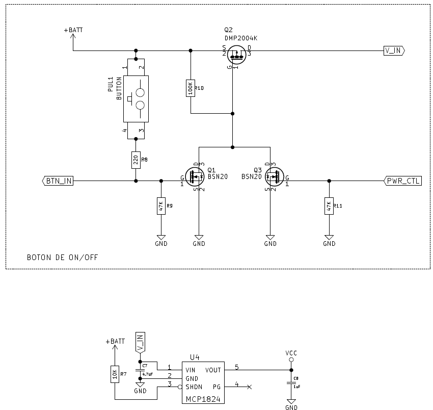
I'm currently working in a circuit which I'm trying to switch on using a button. The main idea is that when button is pressed, the power source gives power to a PIC microcontroller which writes '1' to PWR_CTL, causing the circuit to remain ON. I can use BTN_IN to detect when the button is pressed again for two seconds, and then, write '0' to PWR_CTL and power off the circuit.

The problem is: When the circuit is off, I have about 1.7 V in V_IN, which means to have 1V in the regulator output. This is causing several problems in the rest of the circuit, since it is not completely powered off (in addition I have an undesiderable consumption).

Can anybody suggest a simple soluition to keep the power source completely off?

Thank you!! enter image description here

\$\endgroup\$
6
  • \$\begingroup\$ You might want to watch the eevblog video about soft latching power circuits. \$\endgroup\$
    – PlasmaHH
    Commented Sep 12, 2016 at 9:09
  • \$\begingroup\$ It would be useful to know the voltages at various points in the circuit. What is +BATT, the gate voltages of Q1, Q2 and Q3. Also, are you sure that you connected the mosfets the correct way round? \$\endgroup\$
    – Steve G
    Commented Sep 12, 2016 at 9:21
  • \$\begingroup\$ @PlasmaHH, I can't find that video. \$\endgroup\$
    – Santi
    Commented Sep 12, 2016 at 9:45
  • \$\begingroup\$ @steveG, +BATT is a Lithium battery, ranging 3.3V to 4.2V. When the circuit is suposed to be off, gate voltages are 0V, 3.9V (pull-up to battery) and 0V for Q1 Q2 and Q3. And yes, I'm quite sure I've connected the mosfets in the right way. I have triple-checked them. \$\endgroup\$
    – Santi
    Commented Sep 12, 2016 at 9:54
  • \$\begingroup\$ "I'm currently working in a circuit" Try using tubes instead of transistors. They'll give you more room. \$\endgroup\$ Commented Sep 12, 2016 at 11:25

2 Answers 2

1
\$\begingroup\$

First of all, you will need to understand what's happen. You should measure the following voltages:

  • Q2 gate voltage
  • Q1 and Q3 gates voltage

Because you used pretty high resistance values for your pull-up and down (R9, R10 and R11), you could have non negligible voltages if you have some current leakage, even small ones.

So, when your system is supposed to be OFF:

  • If Q1 and Q3 gate voltages are close enough to 0V, you could end up with these transistors to start conducting, which would cause Q2 to conduct as well, and V_in to be partially powered;
  • If the current leak at Q1 and Q3 is too important, even when they are driven open properly (see the datasheet for maximum leakage current), the voltage drop at R10 could be non negligible, and partially turning Q2 ON. Keep in mind that a 10µA current through a 100k resistance will generate a drop of 1V.

Last solution, if everything should (in theory) work: make sure your board is clean enough.

\$\endgroup\$
1
\$\begingroup\$

The P channel pass transistor (DMP2004) has a source/drain leakage current specified that can be as high as 1 uA - could this be the problem in producing the 1.7 volts when the circuit is supposedly off?

This current may approximately double for every ten celcius rise above ambient. The same problem existswith the other two MOSFETs and this could be starting to activate the pass transistor.

Using a multimeter on some of these high impedance nodes may not be useful because the multimeter input impedance is not infinite and it could disturb what the circuit is doing.

\$\endgroup\$

Your Answer

By clicking “Post Your Answer”, you agree to our terms of service and acknowledge you have read our privacy policy.

Not the answer you're looking for? Browse other questions tagged or ask your own question.