4
\$\begingroup\$

Would it be reasonable to implement a soft ON/OFF button like this?

enter image description here

My design requirements in short:

  • Enable the system power from a single-cell LiPo battery immediately after the ON/OFF button has been pressed.
  • The system power is controlled via an active-high enable pin of a switch mode DC/DC converter, and not switched directly.
  • The system should keep powered on, also during possible microcontroller (MCU) resets.
  • Subsequent button pushes should have no effect on the running device.
  • Button events should be readable by the MCU.
  • The MCU can actively turn off the system, after pressing the power button down for X seconds.
  • Low power usage, and ideally almost no power usage in OFF state.
  • No specialized ICs (and ideally no discrete MOSFETs, preferably a solution that only uses simple digital logics).

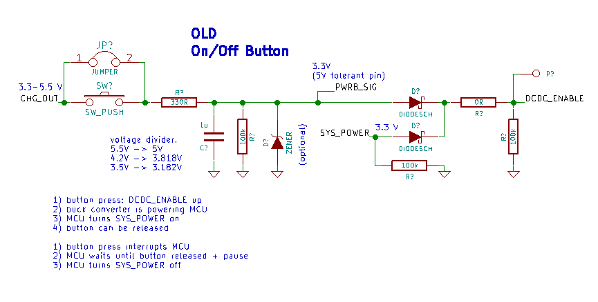
My old attempt looked like that:

enter image description here

To my surprise it works pretty well, but I had two problems with it:

  1. The system turns itself off when the MCU soft-resets itself, i.e. when it loads a new program to RAM from an SD card (SYS_POWER GPIO was reset).
  2. It is common to keep the ON/OFF button pressed for a while until the device shuts down, but that isn't possible with this diode based "OR gate". The button must be released for the shutdown to happen...

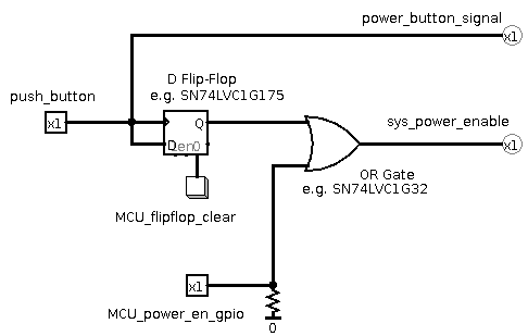
I'm currently trying to find a simpler solution, and sketched up the idea above in Logisim. The key is to use a storage element like a flip-flop.

(One problem I see with that solution is that the flip-flop would need to be powered by the battery directly. - (The flip-flop could possibly replaced by a S-R latch, but invalid states could occur... Or the OR gate could be replaced with three diodes, one additional input connecting the power button directly to the system power enable pin. Then the flip-flop would need to react to the falling edge, and be powered on after system power comes up. But that seems dangerous and overly complicated...))

By the way, I'm currently trying to learn more about electronics and I'm no expert at all. - This is a hobby-level microcontroller project, designed in KiCAD.

\$\endgroup\$
4
  • \$\begingroup\$ "and ideally no discrete MOSFETs" and "Low power usage, and ideally almost no power usage in OFF state." doesn't really go hand in hand. You can get very low power usage with discrete MOSFETs. - If I were you, I'd widen my "ideal" solutions. \$\endgroup\$ Commented Jun 28, 2018 at 2:55
  • \$\begingroup\$ What if all power sources are <3V like charger or Bat ? \$\endgroup\$
    – D.A.S.
    Commented Jun 28, 2018 at 3:44
  • \$\begingroup\$ contact bounce could be a problem. \$\endgroup\$ Commented Jun 28, 2018 at 8:30
  • \$\begingroup\$ Thanks a lot for the hints! Harry: I do agree... the actual reason why I tried to avoid them is because they are tricky to use right :P I'm going to look into a simpler solution today, that uses discrete MOSFETs and diodes, to compare it to the one above... I'm still interested in the one above, since it is so clean and easy to understand... But does it make any sense? I've never seen such a soft button yet. Tony: I think, It wouldn't turn on anymore, and the battery would be drained slowly, until a charger's plugged in, which would be ok I guess. Jasen: Debouncing will be required, yes. \$\endgroup\$
    – rel
    Commented Jun 28, 2018 at 12:30

3 Answers 3

1
\$\begingroup\$

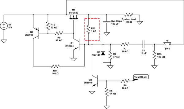
This solution is slightly similar to Cristobols but maybe with a better defined start state and less strain on the MCU pin. This:

schematic

simulate this circuit – Schematic created using CircuitLab

R10, R9 keeps M1 turned off when power is applied. When SW1 is pushed M1s gate is grounded by Q1 and M1 starts conducting to the load. Q1 also activates Q4 so they are latched on. C1 makes a short pulse to the Q1 base, so if the user holds the button pressed Q1 can still be turned off by Q3. The MCU can decide to switch the power off by sending a pulse on Q3. R6 can probably be adjusted to mitigate effects of high impedance/pullups if the MCU goes into reset.

The idea here is to not latch on M1s output since it probably has a bit of capacitance connected to it. An example: if the base of Q1 was connected with a resistor to M1 illustrated by the red boxed R12, Q3 would have to discharge the system capacitors through R12 to shutdown M1.

Edit: Just realized that you're actually controlling the EN pin of a regulator and not switching the load path directly. But I think the suggested circuit would work on an enable pin also.

\$\endgroup\$
11
  • \$\begingroup\$ Thanks a lot for the detailed response! It is really nice and works also for controlling an EN pin of a regulator I think. - The only problem I'm still having (also with the other flip-flop based approach) is that the MCU cannot turn off the regulator while the user keeps the push button pressed. The MCU itself is powered by the DC/DC converter, which will be turned off after taking the GPIO high, before the button is released... so that Q3 turns off and the device on again. To understand it more easily, I've also simulated the circuit in Falstad's circuit JS: bit.ly/2tE646R \$\endgroup\$
    – rel
    Commented Jun 28, 2018 at 23:32
  • \$\begingroup\$ BTW: The same problem occurred while I was trying to make another flip-flop based solution work. Disabling the system power, while the ON/OFF button is pressed isn't possible yet, because it turns on right after disabling it...; also tested in Falstad's circuit JS: bit.ly/2tDYKbm \$\endgroup\$
    – rel
    Commented Jun 29, 2018 at 0:04
  • \$\begingroup\$ An idea that came up to slove this issue would be to add a capacitor, that is charged up by the system power rail (3.3V). A switching element (MOSFET or transmission gate (?) that is normally closed) in series with the button would disable the button input after the 3.3 V rail comes up. The MCU could still read the button, disable the regulator, so that the capacitor would be discharged... - Minor issues here: 1) The button will be disabled after shutdown for a while... 2) System comes up again after holding it down for too long. - Circuit JS: bit.ly/2yTfpwS Does that make any sense? \$\endgroup\$
    – rel
    Commented Jun 29, 2018 at 1:53
  • \$\begingroup\$ I added a "pulse thing" to the Q1 drive so it doesn't matter if the button is kept pressed. \$\endgroup\$
    – Dejvid_no1
    Commented Jun 29, 2018 at 6:15
  • \$\begingroup\$ This is very neat. - I've tested it also in Circuit JS: bit.ly/2tTVisO, and moved the diode D1, so that the base voltage of Q1 cannot fall too low after the button is released (reverse pulse through C1?). And I've also tried to replace the MOSFET M1 with a second PNP transistor (since it is only for signal switching), and added a resistor to its base, to reduce the component count (1x dual NPN, 1x dual PNP and a couple of passive parts). - Do you think that this modifiction makes sense? - I'd be very happy with this or a similar solution, if it works reliably in practice. \$\endgroup\$
    – rel
    Commented Jun 29, 2018 at 13:47
1
\$\begingroup\$

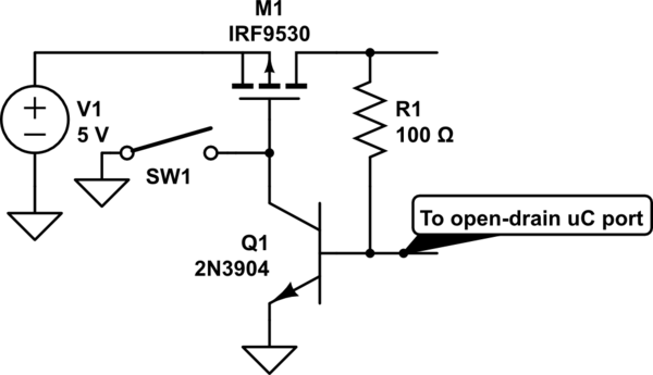
MOSFETs aren't so tricky, especially in on/off applications. Here's an approach:

schematic

simulate this circuit – Schematic created using CircuitLab

\$\endgroup\$
2
  • \$\begingroup\$ Thanks for the input! - Would it make sense to add a pull-up resistor to M1's gate, to prevent it from floating? I've also made a Falstad circuit JS sketch of this, just as an exercise =) bit.ly/2Kep46i \$\endgroup\$
    – rel
    Commented Jun 29, 2018 at 2:40
  • \$\begingroup\$ You're right, it would make it more reliable. I was just trying to show the basics; these exact components might not be ideal for your application either. For example, the 100\$\Omega\$ could probably be several K\$\Omega\$. \$\endgroup\$ Commented Jun 29, 2018 at 12:05
0
\$\begingroup\$

Connecting a push button directly to the CLK input of a flip flop will result in the flop togging multiple times due to bouncing of the switch.

A second thing is that the inputs to a flip flop, the D input in this case, require setup time to be stable at a logic level before the CLK rising edge. As such it will not work to tie the CLK and D inputs together.

A good design approach for this type of switching is to use the push button to turn the power on and then let the MCU be able to read the button state and leave all control for turning the unit off be made by the MCU software. If you use a P-FET to switch the power on then in the off state there does not need to be any current from the battery except for any very low level leakage current when the P-FET is biased in the OFF state.

Two signals from the MCU are required, one to monitor the button state and a second to hold ON the power or shut OFF power. Depending upon how you choose to build the associated circuitry around the P-FET it can sometimes be simpler to add a third MCU signal to the mix and separate the hold-on function from the turn-off control. The circuitry for this kind of thing does not require logic chips. Also the MCU must wake up quickly and one of the first things that the MCU software must do is to assert the hold-on control.

\$\endgroup\$
1
  • \$\begingroup\$ Thanks for pointing out the issues with the flip-flop, and the general hints. This helps a lot! \$\endgroup\$
    – rel
    Commented Jun 29, 2018 at 2:17

Your Answer

By clicking “Post Your Answer”, you agree to our terms of service and acknowledge you have read our privacy policy.

Not the answer you're looking for? Browse other questions tagged or ask your own question.