12
\$\begingroup\$

The MIDI specification suggests a fast switching diode to protect the optocoupler's LED against ESD that could exceed its reverse voltage:
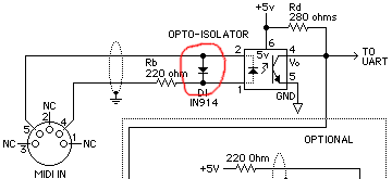
MIDI input, diode highlighted

But this is the only diode used; I could simplify the BOM if I could replace it with some component already used elsewhere in the circuit. So why not use a PN junction of a general-purpose transistor?

Compared to the 1N4148, the 2N3904 has smaller reverse breakdown voltages, but this would not matter in this application because the LED clamps such voltages. Other parameters like capacitance or maximum current are comparable. So this looks as if the transistor would work, wouldn't it?

BJT as diode - choices

And which junction should be used, base/emitter, base/collector, or both? And what to do with the unused junction?

\$\endgroup\$

4 Answers 4

5
\$\begingroup\$

Yes, there is no problem. Just connect collector to base and use that as the diode. No abuse involved. A diode, even an LL4148, is a bit more rugged than a diode-connected transistor but that should not be an issue here.

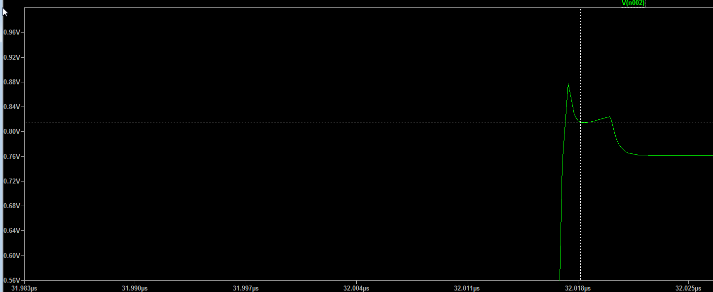
Here is the slight overshoot in the response with the LED open and a 2N3904 connected as I suggested (+/-10V input through a 220R resistor), 10ns rise and fall times simulated in LTSpice with 1ns maximum step size:

enter image description here

\$\endgroup\$
7
\$\begingroup\$

Ferranti's application report E-Line Transistor Applications discusses the various diode connections (p. 70):

Using the ZTX300 (BCW10) as a Diode

Three possible methods of connection are described:

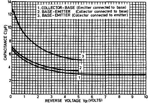
  1. Collector/Base (with emitter connected to base).
    This connection gives a diode with a medium recovery time, small capacitance, and high reverse voltage determined by the collector-base junction.
  2. Base/Emitter (collector connected to base).
    The diode has a short recovery time, small capacitance, and a low reverse voltage determined the base-emitter junction.
  3. Base/Emitter (collector connected to emitter).
    The diode has a long reverse recovery time, a large capacitance, and a low reverse voltage determined by the base-emitter junction.

transistor as a diode connections

Method of   Recovery Time nSec.        Capacitance pF
Connection  IF=IR=10mA. R=50Ω    at zero   at reverse voltage
                                 voltage   -10V      -5V
----------  -------------------  -------  --------  --------
 1            89                   7        3
 2             2.7                 7                  3.5
 3           244                  13                  5.5

The recovery time quoted is the interval between the negative input pulse attaining 10% of its final value and the reverse current attaining 10% of its maximum value.

The graph shows the variation of capacitance with reverse voltage.

variation of capacitance with reverse voltage

So connection 2 would give the behaviour most similar to the 1N4148.

\$\endgroup\$
3
\$\begingroup\$

I honestly haven't tried it. So I'm going to go "on theory."

You probably can use the BC or BE junction. I wouldn't recommend diode-connecting the BJT, though. If you are just looking for speed, and since you aren't looking for reverse voltage tolerance, you'd probably get more \$t_{rr}\$ out of the BE junction. Because the base is so thin (by design), I would expect very fast responses -- on the order of fast switching diodes. Leakage will almost certainly be a lot better, too. Especially with the BE junction.

Take a look at figure 35 in the OP77 datasheet from Analog. You'll see something like what you are talking about. However, they are using the BC junction, probably because of the larger breakdown voltage. (The BE junction usually doesn't tolerate much -- 5 or 6 volts, often.)

However, as an ESD diode? I have no idea what a \$20\:\textrm{kV}\$ static zap might do.

\$\endgroup\$
0
\$\begingroup\$

I think the most alternative to the diode is the schematic number 2, a confederation to be taken is that you should use a resistor between Emitter and the base to protect the transistor.

\$\endgroup\$
5
  • 1
    \$\begingroup\$ Protect against what? Why wouldn't a diode need the same protection? \$\endgroup\$
    – CL.
    Commented Sep 24, 2016 at 19:03
  • \$\begingroup\$ Normally both diode and transistor need a current limitation resistor because they could be blown out through Jul-effect. \$\endgroup\$
    – kld_rm
    Commented Sep 24, 2016 at 19:11
  • 1
    \$\begingroup\$ @kld_rm I think you might want to elaborate on "Jul-effect" did you perhaps mean Joule Effect? \$\endgroup\$
    – Sam
    Commented Sep 24, 2016 at 21:36
  • \$\begingroup\$ @Sam yes I do, I meat Joule-effect. Thanks \$\endgroup\$
    – kld_rm
    Commented Sep 25, 2016 at 18:57
  • 1
    \$\begingroup\$ We usually just say I2R (or resistive losses) rather than the joule effect, engineers shorthand everything, that's why you're more likely to hear an older engineer calling a 3.3 kilo ohm resistor a 3 'kay' 3 resistor, or that they need a 10 'mike' or a 100 'puff' cap, we're too lazy to use the full words ;) \$\endgroup\$
    – Sam
    Commented Sep 25, 2016 at 23:46

Your Answer

By clicking “Post Your Answer”, you agree to our terms of service and acknowledge you have read our privacy policy.

Not the answer you're looking for? Browse other questions tagged or ask your own question.