3
\$\begingroup\$

I have the Freetronics Eleven, which is 100% compatible with Arduino Uno. Ultimately, I want to make a foot pedal switch that connects to a digital pin on the arduino so that a LOW is read when the pedal is pressed, and a HIGH is read when the pedal is released, or vice versa.

At the moment I'm just trying to test making a switch of the same behavior by sticking wires in the pins and connecting them together. I've tried connecting and disconnecting pin 2 and gnd, pin 2 and 5v, pin 2 and pin 12 etc. with pin 2 set to input.

What is the correct setup to make a basic switch? Which pin do I connect to which to make it so when the pins are connected one reads low instead of high, or vice versa?

EDIT: Thanks for telling me about the pull-up resistor. I have since discovered via google that the arduino pins have built-in pull-up resistors. For others who come along this problem, this is how you enable them:

pinMode(10, INPUT); // set pin 10 for input
digitalWrite(10, HIGH); // set pull-up resistor on pin 10

then to use:

if (digitalRead(10) == LOW) // pin 10 is connected to gnd
    doSomething();
else // pin 10 is not connected to gnd
    doSomethingElse();
\$\endgroup\$
3
  • \$\begingroup\$ I would say that a switch for Arduino is not different from a switch for anything else. \$\endgroup\$
    – clabacchio
    Commented Feb 16, 2012 at 10:21
  • \$\begingroup\$ arduino.cc/en/Tutorial/Switch ladyada.net/learn/arduino/lesson5.html \$\endgroup\$ Commented Feb 16, 2012 at 11:08
  • 1
    \$\begingroup\$ The internal pull-ups are very weak. There is a good deal more that probably ought to be done, especially if you're connecting this footswitch on a long wire. A capacitor to slow the transition a bit, an inline resistor or buffer to protect the Arduino, and debouncing the switch in software are all things you should look into. \$\endgroup\$ Commented Feb 16, 2012 at 14:19

1 Answer 1

5
\$\begingroup\$

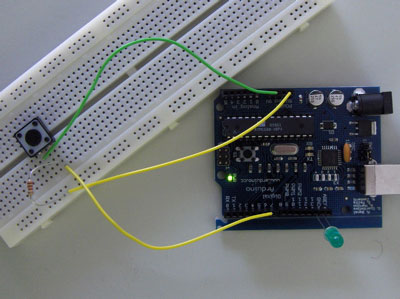
What you need is a pull-up resistor.

enter image description here

The Arduino whebsite has a nice tutorial (with software) on using a pushbutton.

We connect three wires to the Arduino board. The first goes from one leg of the pushbutton through a pull-up resistor (here 2.2 KOhms) to the 5 volt supply. The second goes from the corresponding leg of the pushbutton to ground. The third connects to a digital i/o pin (here pin 7) which reads the button's state.

enter image description here

\$\endgroup\$
1
  • \$\begingroup\$ Beat me to the punch, I was typing an answer as yours popped up :) @Nicholas Grasevski, Another way to visualize this with a schematic. 2k2Ohm is a little stiff but will work just fine .I usually prefer 4k7-10kOhm depending on what I have on hand. \$\endgroup\$ Commented Feb 16, 2012 at 4:35

Your Answer

By clicking “Post Your Answer”, you agree to our terms of service and acknowledge you have read our privacy policy.

Not the answer you're looking for? Browse other questions tagged or ask your own question.