2
\$\begingroup\$

I want to use serial communication between a master and multiple slaves.

I've already connected the RX of the master to the TX pins of both slaves, and vice versa (thus connected the TX pin of the master to the RX pins of both slaves). I also connected the GND pins.

But now I got weird characters when I open the serial monitor window.

Now how do I properly connect a master Arduino device with at least two slave Arduino devices using the RX and TX pins? Do I need to connect 5V pins?

PS: I see a lot of words like "SPI" and "I2C", and people start using terminology. But I'm not thát experienced, so please, if using the terms, explain them.
Another PS: I want the Arduino devices to use power from the master Arduino device.

\$\endgroup\$
1
  • 1
    \$\begingroup\$ You can connect one TX pin to multiple RX pins. When you connect multiple TX pins to one RX pin, you get in trouble as the signal from one TX interferes with the other. You need to use multiple UARTS (serial ports) on the master to separate ones connect to each slave. \$\endgroup\$
    – DoxyLover
    Commented Feb 4, 2015 at 1:59

3 Answers 3

6
\$\begingroup\$

Now how do I properly connect a master Arduino device with at least two slave Arduino devices using the RX and TX pins? Do I need to connect 5V pins?

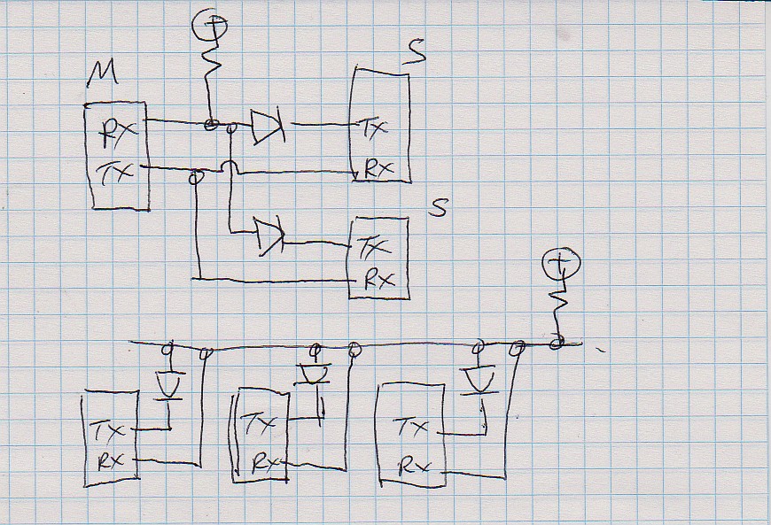
Poor-man's networking:

The circuit below is "naughty" in the extreme but can be made to work "well enough".
You can do the same thing using formal gates.

Top circuit:

Master + N secondaries.
Master is always heard by all secondaries.
Master can hear any one secondary.
Secondaries cannot hear other secondaries.
Multiple secondaries transmitting simultaneously corrupt both signals.

Master RX is pulled up by resistor.
Either slave can pull Master RX low by setting their TX low.
Only one slave can :"talk" at a time if corrupt transmissions are to be avoided. Max limited by time constant of R plus circuit capacitance.
Too low an R cannot be pulled down properly by TX.

Bottom circuit: All peers.

Any can send (one at a time).
All will receive anything sent.
Sender will receive own transmission and can judge if transmission was corrupted.

Useful for eg Pure-ALOHAnet or slotted-ALOHAnet operation.
Or for that matter token ring, round robin or most other network systems. Even CSMA/CD

enter image description here

Pullup resistor value left as an exercise for the student.

Polarity shown assume TX idle level is high.
Reverse diode polarities and use pulldown for TX idle is low.

\$\endgroup\$
2
  • \$\begingroup\$ I was about to suggest something similar but you beat me to it! I just finished a design that does something very similar, except that there are opto-isolators at each node. Nonetheless, it's a one-wire half-duplex scheme very much like what you have shown above. \$\endgroup\$ Commented Feb 4, 2015 at 4:40
  • \$\begingroup\$ FWIW - the opto-isolated scheme I mentioned above works well at 2400 baud with 200 meters of a shielded twisted pair cable (+5V, signal, shield is ground). \$\endgroup\$ Commented Feb 4, 2015 at 4:42
5
\$\begingroup\$

Don't connect the TX pins together. When one slave arduino is driving its TX to logic high and the other arduino is driving its TX to logic low, the resulting voltage is not a valid logic level -- this is why you're getting invalid characters.

Insted, buy a prebuilt RS-485 arduino shield for each of your devices. Details below...

The TX/RX isn't designed to support multiple slave devices; it's just a connection between two points. The TX output is always driven, and there can be only one driver.

To properly connect multiple slave devices, you need an interface that's actually designed to support multiple drivers.

The Arduino TX/RX pins that you're using, are commonly called RS-232, although that's not quite accurate. RS-232 is a very simple kind of network that connects two devices. One device is called the DCE and the other device is called the DTE. Don't worry about what those names mean; they used to mean something back in the dark ages when people connected wired telephone handsets into acoustic telephone modems (http://en.wikipedia.org/wiki/Acoustic_coupler) The only thing is that one device transmits on the TXD wire and listens on the RXD wire, while the other device transmits on RXD and listens on TXD. This gets confusing, since we like to connect wires that have similar names, so we often use a type of connection called a Null Modem -- the TX output of one device drives the RX input of the other device, and vice versa.

(I'm skipping over some details about how RS-232 signals use higher voltages than the CMOS logic levels -- it's not just a direct logic connection.)

But the limitation of a null modem is that it only connects two devices. It can't support a network of three devices, because the cable connection can't know which device is signalling valid data and which device is idle. That requires a newer kind of serial network called `RS-485'.

The RS-485 standard requires using a special type of level translator, you don't just connect the logic level TX/RX signals. This RS-485 level translator takes care of driving the interconnect in such a way that it allows sharing the connection between multiple devices. You still have to be careful about not allowing devices to transmit at the same time (called a Collision), but since you've designated one device as the master and the other devices as slaves, that shouldn't be a problem. The master device decides which device gets to talk on the bus.

Since you're an Arduino user and not very experienced with electronics, the simplest way for you will be to purchase a prebuilt RS-485 arduino shield.

You mentioned I2C (also less commonly abbreviated as IIC), which is a 2-wire open-drain interface standard originally defined by Philips corporation. Google i2c bus specification for details. You could probably accomplish what you're trying to do with either RS-485 or I2C, but RS-485 is closer to what you're using now.

You mentioned that you want to power the slave devices from the same power supply that powers the master device. (They should already be using the same ground return connection in any case.) If the master arduino is being powered from USB, that should be OK as long as the total supply current drawn by all three boards does not exceed the rated load current. If that happens, you'll know because your windows PC will shut off the USB port.

\$\endgroup\$
2
  • \$\begingroup\$ What you haven't mentioned when talking about RS-485 is the direction control that is required at each node. You can do this in hardware if needed (Jan Axelson published a neat circuit that works well) but direction control is normally handled by the microcontroller. \$\endgroup\$ Commented Feb 4, 2015 at 4:46
  • \$\begingroup\$ @DwayneReid Direction control is only needed for half-duplex RS485. If you have separate full-duplex TX & RX pairs then its not necessary. \$\endgroup\$
    – brhans
    Commented Feb 4, 2015 at 14:21
-3
\$\begingroup\$

https://www.arduino.cc/en/Tutorial/TwoPortReceive

it goes over setting other digital pins into other TX and RX pins.

Frosty0_0

\$\endgroup\$
0

Your Answer

By clicking “Post Your Answer”, you agree to our terms of service and acknowledge you have read our privacy policy.

Not the answer you're looking for? Browse other questions tagged or ask your own question.