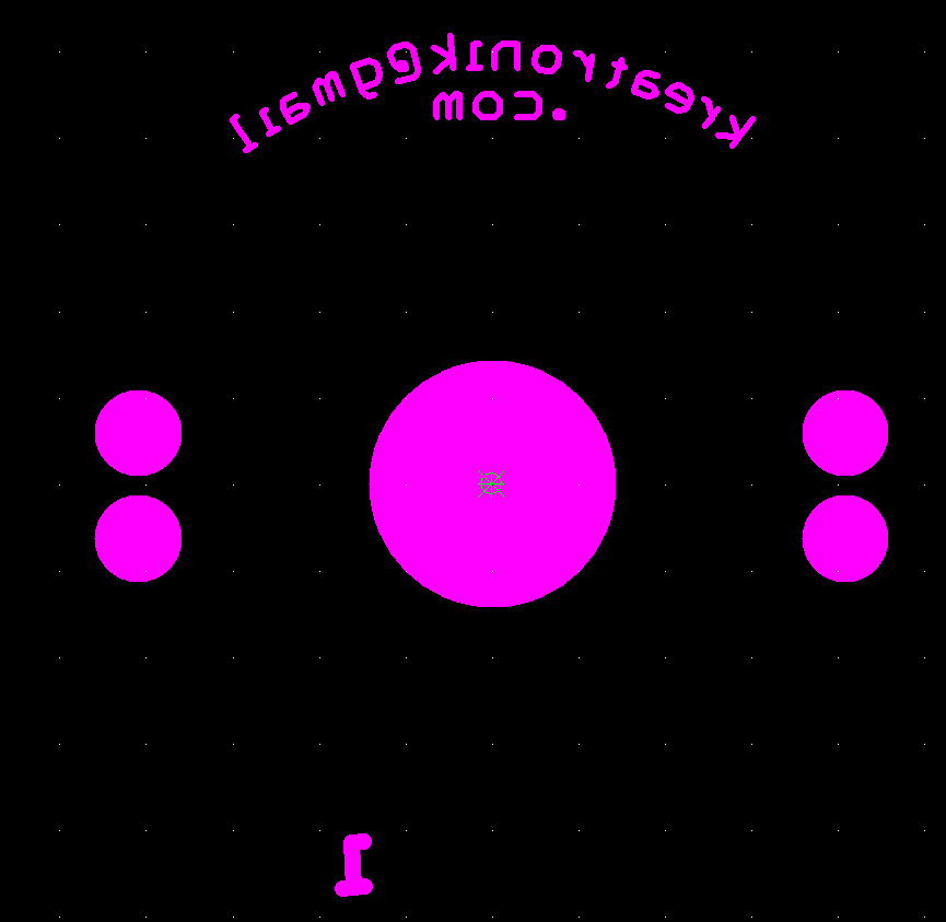
I have my email address embedded in the soldermask layer. When checking the generated Gerber data, the dots on all the "i"s are missing.
-
1\$\begingroup\$ Can you please provide a snapshot of the Altium? and the gerbers? \$\endgroup\$– Jesus CastaneCommented Nov 9, 2016 at 14:31
-
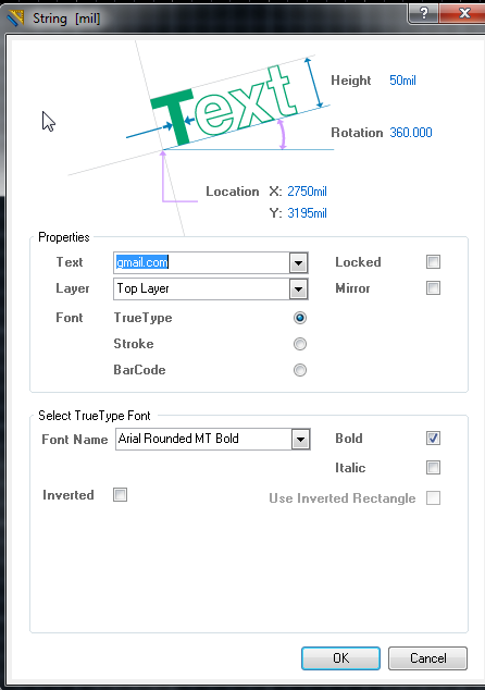
1\$\begingroup\$ Did you use the default stroke font or a Truetype font? Especially if the latter, the conversion probably has a lower limit on size for conversion to Gerber elements. \$\endgroup\$– Spehro 'speff' PefhanyCommented Nov 9, 2016 at 16:32
-
\$\begingroup\$ It's "Stroke" Font with "Default" setting. Also as you can see now, making the letter bigger doesn't solve the problem. \$\endgroup\$– KreatronikCommented Nov 9, 2016 at 22:13
2 Answers
I can confirm that the problem exists.
Changing the font to Truetype can avoid the issue.
Maybe you should open a ticket with Altium support.
-
\$\begingroup\$ There are already a few tickets open about this on "Altium Bug Crunch" bugcrunch.live.altium.com/#Bug/2848 or this bugcrunch.live.altium.com/#Bug/6200 You can vote for them if you want. Free registration needed. \$\endgroup\$ Commented Nov 10, 2016 at 11:28
-
1\$\begingroup\$ From my experience, True Type font works quite well on Altium regarding Silkscreen text and i assume on soldermask as well \$\endgroup\$ Commented Nov 10, 2016 at 11:31
Gerber files are based on the concept of exposing a film with light that passes through an aperture. There are commands to select an aperture, to "flash" that aperture at a single point (e.g., to create a pad or other symbol), or to follow a path while the aperture is open (to draw a trace in copper or silkscreen).
It's probable that your simple stroke-based font uses the regular path command to create the dot for the "i", but the start and end points are the same. The problem is that many Gerber-creation tools will simply optimize out zero-length paths, because normally they don't do anything useful. (They're often created at the junction of two other paths.)
The fix would be to convert zero-length paths to flash commands — but this would be up to the software tool vendor to implement, and it would have to be done fairly selectively; e.g., only in the font-drawing part of the software. They probably don't see it as enough of a priority to put any effort into it.
A workaround would be to redefine the zero-length paths in the font file to have some tiny length — like they did for the period glyph (it's really a little box shape).
-
\$\begingroup\$ I wonder if it's accessible. Altium sez: "The Stroke fonts are built into the software and cannot be changed." \$\endgroup\$ Commented Nov 10, 2016 at 23:53


