5
\$\begingroup\$

I have a learning opportunity that I need some help with :)

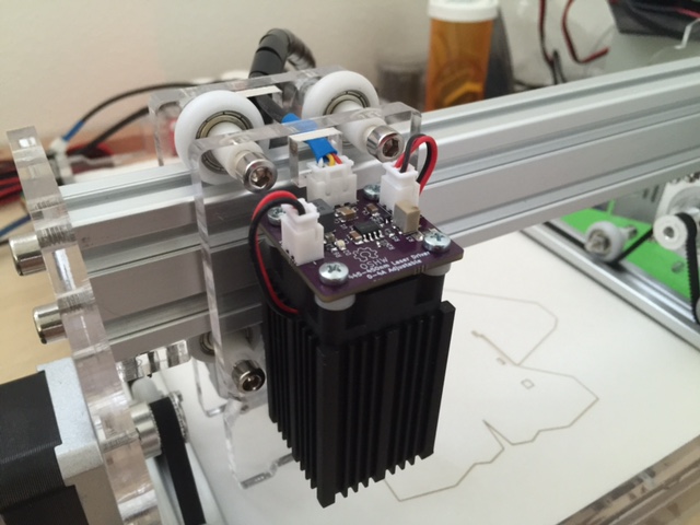
I have current regulator design I put together using the LED2001 IC for driving laser diodes. This is mounted on top of a heatsink module which is mounted to an open frame CNC machine.

Here are the Kicad source files. Kicad Source

Here is an image of it on my machine. enter image description here
The issue that I'm having is that when power is first applied to the board, the dim/enable pin needs to be held high for a brief period before the output of the LED2001 will operate on pulse widths of 1-99% (0% being 0vdc & 100% being 5vdc).

If I don't apply this technique when I first power it on, the output will not turn on until I go above 25% on the pulse width. When cutting stuff this is not a problem as the power is usually set to 100% for the cut opperation but when I'm engraving an image and the start of the engraving happens to be in a light area of the image it will not turn on the laser until it reaches a dark part of the image.

At first I thought it might be an issue with my design but I have since found references to similar designs that seem to indicate that this has something to do with the LED2001 IC.

A suggestion was made to me to disable the output while holding the dim pin high for a brief period at start up (to let the caps charge) and then bring the dim pin low and then enable the output, allowing the PWM signal to control the output after that.

I could slap a mcu on the board to do this but I thought that this would be a good opportunity to learn how to accomplish this without using a micro. I have been searching google for ideas but I don't think I'm using the right key words.

If this is trivial and you want to post a schematic, that is fine. I'll take it and try to learn how it works. OR, if you don't mind pointing me in the right direction or helping me learn the parts that would make this work, I can certainly do the research.

Thanks John

Edit: Here are some screenshots from my O'scope.

  1. 16% PWM after applying power to the board.

https://i.sstatic.net/cs93p.png

  1. 97.3% PWM, not quite fully on yet..

https://i.sstatic.net/h5fqn.png

  1. 97.7% PWM, the driver is on and full PWM range is available.

https://i.sstatic.net/HhGkI.png

  1. back to 16% PWM.

https://i.sstatic.net/oV1Kc.png

Edit: since LTSpice didn't have a NOR gates built in, I found an example using some inexpensive BC817 BJTs. Here is what I came up with that seems to work ok based on the feedback provided in the comments.

I ended up with two NOR gates and one NOT gate which seems to do what I need it to do. When the device is powered on, it should hold the DIM pin high for about 1.5ms and then return back to 0V and stay there until the PWM signal is present, at which time it will control the DIM pin.

The output of the first NOR gate is also used to offset the feedback pin voltage at startup which should limit the output current and basically shutting off the output without adding a mosfet as a switch inline with the output.

Here are some screenshots from LTSpice.

https://i.sstatic.net/h9JQs.png

https://i.sstatic.net/l7kD8.png

https://i.sstatic.net/AxG5p.png

\$\endgroup\$
6
  • \$\begingroup\$ Define time for " held high for a brief period" THis can easily be done in software or hardware with an RC controlled one shot gate.. without burning out Laser from excess pulse width but sufficient to start at low PWM without hysteresis. 1us? 1ms? \$\endgroup\$
    – D.A.S.
    Commented Nov 10, 2016 at 19:19
  • \$\begingroup\$ Thanks, I'll google up on RC controlled one shot gates. The pulse time needed is about 1.5 to 2ms. \$\endgroup\$
    – iceman1979
    Commented Nov 10, 2016 at 22:08
  • \$\begingroup\$ Do you need to switch the output off while this is happening as well? \$\endgroup\$ Commented Nov 10, 2016 at 23:57
  • \$\begingroup\$ Yes the output needs to be switched off so the laser does not come on. :) \$\endgroup\$
    – iceman1979
    Commented Nov 11, 2016 at 2:31
  • \$\begingroup\$ I took a look at the datasheet. Section 5.3 Soft-start explains the issue. During the initial DIM-high period, one possible way to trick the device not to run may be to raise the FB pin voltage. That can be accomplished by couple of summing resistors and a transistor to inject some current. That way you do not need to insert an extra device (e.g. MOSFET) into the power path. \$\endgroup\$
    – rioraxe
    Commented Nov 11, 2016 at 11:03

2 Answers 2

1
\$\begingroup\$

enter image description here

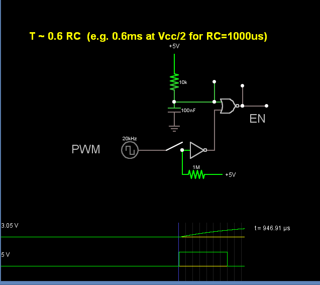
Here is an example the inverts your PWM twice and gives a 600us one shot to EN

\$\endgroup\$
19
  • \$\begingroup\$ That's definitely a move in the right direction. Let me add a little more detail on how it is used. \$\endgroup\$
    – iceman1979
    Commented Nov 10, 2016 at 22:22
  • \$\begingroup\$ The machine gets turned on and then the user sits down at his/her computer and connects to the machine through a USB virtual com port. When the user is ready to start the engraving/cutting process, they will click a button that starts streaming the GCODE to the machine. The PWM signal will only be sent to the laser when it is in the process of engraving. Since the PWM signal turns the laser on and off, any delays will be seen in the engraving. This is why I was thinking it needed to happen at start up so that when the engraving process starts, there is no impact to the work. \$\endgroup\$
    – iceman1979
    Commented Nov 10, 2016 at 22:27
  • \$\begingroup\$ So in a nutshell, this special power on start up cycle needs to happen well in advance of any PWM signal being seen on the dim pin. Thanks for the example. I have some homework to do now :) \$\endgroup\$
    – iceman1979
    Commented Nov 10, 2016 at 22:36
  • \$\begingroup\$ The circuit above will do what you asked for using 2 NOR gates ( 1 NOR gate as a inverter) You dont need the switch or pulldown R.. THat is just your virtual software switch. Just increase C for the ms required. I wonder if you have actually measured this characteristic on a scope and understand why it is needed. \$\endgroup\$
    – D.A.S.
    Commented Nov 10, 2016 at 23:08
  • \$\begingroup\$ So something like this? link I'll play with this in ltspice tonight and see if I can figure it out :) \$\endgroup\$
    – iceman1979
    Commented Nov 10, 2016 at 23:16
0
\$\begingroup\$

If I understand your problem correctly you could also solve it in software only. Just have the very first command always send a very very short 30% intensity signal either off on the side or on the location of the first engraving place.

\$\endgroup\$
4
  • \$\begingroup\$ For my personal use I have a macro setup in one of the software packages I use with the laser that does that for me. Its ok for testing and my personal use but I'll need to resolve this before final release since I won't have control over what software people use and IMO it just needs to work for them. Thanks \$\endgroup\$
    – iceman1979
    Commented Nov 10, 2016 at 22:13
  • \$\begingroup\$ @iceman1979 is it the 1st pulse that needs to be stretched or power EN pulse can have some idle between 1shot EN and PWM? \$\endgroup\$
    – D.A.S.
    Commented Nov 10, 2016 at 22:24
  • \$\begingroup\$ Typically there shouldn't be a PWM signal when the device is powered on so the default state of that pin would be low due to the 10K pull down resistor. I need to provide an initial "manufactured" pulse to the enable pin on power up for a short time and then release it to its default state and allow normal PWM to control the enable pin. \$\endgroup\$
    – iceman1979
    Commented Nov 10, 2016 at 23:00
  • \$\begingroup\$ I did some googling for one shot gates and found an article on a non-retriggerable one shot circuit. This might do what I need. Then for the output, I'm thinking I could reverse the output of the one shot and use that to keep the output disabled with a mosfet that can handle the 4A current requirements of this design. Thoughts? \$\endgroup\$
    – iceman1979
    Commented Nov 10, 2016 at 23:05

Your Answer

By clicking “Post Your Answer”, you agree to our terms of service and acknowledge you have read our privacy policy.

Not the answer you're looking for? Browse other questions tagged or ask your own question.