0
\$\begingroup\$

enter image description here

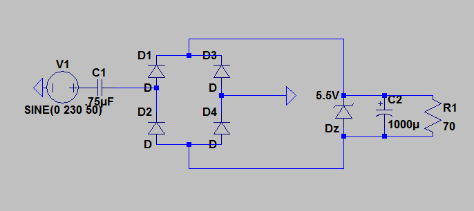
This is based on a design I found somewhere , I just wanted to know whether this is a good idea ,I intend to use this to power a microcontroller and a 70 ohm 5 V relay . The cap c1 limits the current to about 200 mA , well below the 500 mA rating of my zener diode . Without the zener diode , it looks like there would be about 7 volts across r1 which the zener should regulate . Ripples might be a problem though but I don't think it should affect switching that much , I'll also add a flyback diode to this .

Also , I get it that no insulation is a bad idea in general but I need this to be cheap and small . If anyone has got any better idea , I'll be happy to hear .

edit: C1 should be 3 uF

\$\endgroup\$
2
  • 4
    \$\begingroup\$ Generally, if you're asking whether a transformer-less power supply is a good idea, then it's not. \$\endgroup\$
    – Colin
    Commented Dec 14, 2016 at 13:24
  • \$\begingroup\$ Press Alt and click on Dz see how much power the components are using and see if they are exceeding their power rating. \$\endgroup\$
    – Voltage Spike
    Commented Dec 15, 2016 at 22:26

4 Answers 4

2
\$\begingroup\$

I've used this type of design before but it should only be used with care and packaged in such a way so that nobody can easily access any connections - all connections have to be regarded as lethal.

I would add a current limiting resistor in series with the input capacitor because you cannot rule out fast transients occurring on the incoming AC supply and this could cause very large current peaks and potentially destroy the zener and then you have a knock-on problem if it goes open circuit.

Clearly also your diodes need to be rated at the correct reverse potential for AC mains in your neck of the woods.

C1 does seem excessive at 3uF - it's impedance at 50 Hz will be about 1000 ohms and, from a 230 V AC supply will draw a standing current of about 220 mA RMS - that's quite a lot of bad power factor load but if it's a one-off then probably OK.

\$\endgroup\$
10
  • \$\begingroup\$ Would touching point after the zener be alright ? It would only be 200 mA and that too at 5 Volts . \$\endgroup\$
    – Vrisk
    Commented Dec 14, 2016 at 12:55
  • 3
    \$\begingroup\$ @AnirudhGanesh No, any point on that circuit is liable to be at a lethal potential. Just try simulating it and see what voltages are produced relative to ground (neutral) then swap live and neutral and see what is produced - nobody can guarantee that neutral is earthed so there is no protection offered by this circuit against electrocution. \$\endgroup\$
    – Andy aka
    Commented Dec 14, 2016 at 12:57
  • 1
    \$\begingroup\$ @AnirudhGanesh: imagine someone taking your devices power plug and turning it 180° around and plug it in again, now neutral and live are swapped. Also certain countries have certain voltages where you basically have two phases. \$\endgroup\$
    – PlasmaHH
    Commented Dec 14, 2016 at 13:33
  • 1
    \$\begingroup\$ Yes that happens with these types of power supply and that is why (unless your circuit has no grounded inputs and can float up to 230V) it's best to use an isolating transformer. Try ebay - you only need a few wats and it won't be big but it will be bigger than the current design. \$\endgroup\$
    – Andy aka
    Commented Dec 14, 2016 at 14:19
  • 5
    \$\begingroup\$ "Would touching point after the zener be alright ? It would only be 200 mA and that too at 5 Volts." - If you have to ask this, stay far away from power supplies like these. \$\endgroup\$
    – marcelm
    Commented Dec 14, 2016 at 16:34
2
\$\begingroup\$

Subject to certain precautions, it's not too bad. As long as you appreciate the lack of isolation means it must be double isolated from any possibility of being touched.

C1 must be a mains rated type, like an X2. They have specially designed electrodes to survive the 1500v transient over-voltages that happen all the time on mains.

C1 should have a small resistor in series with it to limit the inrush current that could flow when you first turn on. It protects the diode bridge from overcurrent. If your bridge consists of something like 1N400x series diodes, they can stand 30A for one half mains cycle, so an 8ohm resistor would be enough, and not get too hot under normal operating conditions.

As Dave Tweed points out below, a large resistor across C1 is also a good idea, to bleed off charge, to avoid surprising you a few minutes after disconnecting it.

The diode bridge only needs to be rated for the zener voltage. If that fails, you will lose your load and C2.

\$\endgroup\$
3
  • \$\begingroup\$ C1 should also have a large resistor in parallel with it, to bleed off any charge left on it when the circuit is disconnected from the mains. \$\endgroup\$
    – Dave Tweed
    Commented Dec 14, 2016 at 13:11
  • \$\begingroup\$ The reason for @Dave's bleeder resistor suggestion is that otherwise you could have a fair sized capacitor charged to +/-400VDC and essentially connected to the AC plug pins when you yank it out of the wall. \$\endgroup\$ Commented Dec 14, 2016 at 20:10
  • \$\begingroup\$ @SpehroPefhany the bleeder is not going to reduce the surprise you get a second after pulling it out of the wall, and touching the plug \$\endgroup\$
    – Neil_UK
    Commented Dec 15, 2016 at 7:40
2
\$\begingroup\$

I think you'd be better off using a wall-mount power supply. They're widely available (my local grocery store carries them) and inexpensive (< $10 US). If "small" is important to you, you might be surprised at how big an across-the-line rated capacitor is. You've probably seen them in home appliances without noticing their values. They're about the same size as the smallest power transformers.

Adding a few thoughts:

All the current estimates - in the question and in the answers - are too high. It's easy to calculate the maximum current that would be drawn by a worst-case load (a short-circuit). In each half cycle the voltage across C1 changes by 325 volts (230 Vrms is 325 Vp), which pushes 975 microcoulombs through the capacitor. This happens every 10 msec., so the average DC current is 97.5 ma. The actual current will be less, but not a lot less, since the peak voltage seen by C1 is reduced by two diode drops and 5.5 volts.

Troubleshooting the circuit could be exciting. For example, if you probe either side of Dz (or its parallel cohorts) with a scope, you'll see a (more or less) square wave, with an average value depending on which side of Dz you chose. Don't even think of grounding the probe.

There's a similar circuit that uses fewer components: connect the load side of C1 to the cathode of a zener whose anode is grounded (actually neutraled - neutered?). Then, getting back to the zener's cathode, connect it to the anode of a rectifier whose cathode supplies the load. The load return would be neutral. The ripple would be higher, for a given C2, but it saves three rectifiers. Not a big parts cost savings, but it uses less room on the schematic, which could lead to using less paper. Spotted owls will thank you.

Electric shock is not a big consideration. All modern power tools, for example, have plastic cases, and don't use the ground connections provided by electrical outlets.

Damage from power line transients is, really, a significant consideration. Neil_UK mentioned 1500 volts. I read 6000 volts somewhere.

The biggest worry is some component failing and starting a fire. That hazard, and the other two just mentioned, are best dealt with by making them someone else's problem. That was the reason for my first round answer: wall-mount PS.

Your concerns with size and cost suggest you're considering producing more than a handful. You should start your design by reviewing requirements for certification by agencies like UL. It used to be said, in antiquity (1970s) that the only requirement for starting a power supply business was having a two car garage and only one car. That didn't mean that there were a lot of PS makers, but that the scope of the effort was usually underestimated.

\$\endgroup\$
2
  • \$\begingroup\$ I have a 250 V polyester film cap , it isn't as big as a wall wart . \$\endgroup\$
    – Vrisk
    Commented Dec 14, 2016 at 13:51
  • 2
    \$\begingroup\$ Neither is it remotely suitable. Stop before you hurt yourself or someone else. \$\endgroup\$ Commented Dec 14, 2016 at 20:14
1
\$\begingroup\$

This kind of supply is acceptable IF everything that is being powered by it is always well insulated from the user. This is the case, for example, in a LED lightbulb where the whole thing is sealed.

A shunt regulator is also rather wasteful with power. You said the current is limited to about 200 mA, but is actually much less. I get 50-60 mA. If it really was 200 mA, then this would be constantly dissipating (200 mA)(5.5 V) = 1.1 W. That may not be a big deal in terms of overall energy consumption, but is enough that you have to think about the thermal issues. That's more, for example, than a TO-220 package in free air, especially inside a small closed box, can safely dissipate.

Again, you need to look at C1 more carefully. The 70 Ω load will draw 79 mA at 5.5 V, but you're only going to get about 54 mA with the 750 nF you show.

Another issue is that this kind of capacitive coupling transfers current largely as a function of the derivative of the voltage. That's fine when the voltage is a sine, and most of the time it will be. However, spikes happen. These have large dV/dt, so can cause large current surges thru the capacitor. A resistor in series with the cap can help with this, but it's a tradeoff with causing even more dissipation during normal operation.

\$\endgroup\$
1
  • 1
    \$\begingroup\$ Whoever downvoted this, it would be useful to explain what exactly you think is wrong, misleading, or badly written. I have re-read this answer and still think it is correct. \$\endgroup\$ Commented Dec 14, 2016 at 18:24

Not the answer you're looking for? Browse other questions tagged or ask your own question.