1
\$\begingroup\$

I have an old amplifier that was home-built by someone, and I'm trying to reverse-engineer the power supply (for a start) to understand how it works, and to educate myself.

However, I cannot get the supply to regulate, the simulator is showing very odd behavior that I do not understand. The reverse-engineered circuit looks as follows:

D2 is (I believe) a 22 V Zener (this part is marked as 1N969B), and it looks like this is used to set the emitter of Q1 to a stable voltage. R5/R6 (the PCB includes a pot as well) then puts about half the output voltage on the base of Q1.

If the output is high I assume Q1 activates, so that the Darlington pair Q2/Q3 deactivates to regulate the output down. I measured the input voltage to be around 47 V. I haven't measured the output voltage (the board is removed from the amp), but I would expect this to be about twice the Zener voltage of D2, right?

The simulator disagrees with me however, there is no regulation at all, and for reasons beyond my understanding it shows over 500 mA current through D2, the emitter of Q1, and the base of Q1, and then this current just disappears into nowhere. R5, R6 and C4 show no current at all.

Does this circuit look familiar to anyone, and does my understanding as described above make sense, or is it completely wrong?

Note: as to the parts, I'm unsure about the value of C4, but it looks like a decoupling cap for the transistor.

Also, the whole of R1, R2, and C2 totally doesn't make sense to me. C2 looks like a cap, and is marked as "22/100V", and includes polarity markings, so it has to be a polarized capacitor.

\$\endgroup\$
3
  • \$\begingroup\$ Add your simulated schematic (leave the original of course). It looks like it should regulate at about 45 volts to me. Please don't use open/close hydraulic valve terminology when describing a transistor. Use open to mean open-circuit and short to mean a short-circuit. Better still; use activate and deactivate but not hydraulic terms. \$\endgroup\$
    – Andy aka
    Commented Jan 8, 2022 at 11:54
  • 1
    \$\begingroup\$ This circuit should work. The output voltage will be around (1 + R6/R5) *(Vbe +Vz). AS for the simulation try to increase the simulation time to 1s or more due to large capacitors present in the circuit. learnabout-electronics.org/PSU/psu22.php \$\endgroup\$
    – G36
    Commented Jan 8, 2022 at 11:55
  • \$\begingroup\$ @Andyaka this is the exact circuit as simulated. I use eeschema + ngspice. I've simulated multiple seconds, but I don't see any regulation: the ripple on the output is the same as the ripple in the rectified input ... so it's probably simulation error due to incorrect/wrong models for the transistors? \$\endgroup\$
    – Michel
    Commented Jan 8, 2022 at 12:29

1 Answer 1

5
\$\begingroup\$

R5/R6 are the feedback network, dividing the output voltage by 2. This feeds the base of Q1 which compares this voltage to the 22V zener used as reference. So the output voltage is set to (22V+0.6V)*2 = 45.2V.

When output voltage is too high, Q1 passes more current, bringing down Q2's base and reducing output voltage.

C4 is the Miller compensation cap for the feedback loop. It reduces gain at high frequency to prevent oscillation.

R1,R2,C2 form a lowpass filter to increase PSRR at high frequency.

I've simulated it and it seems to work fine.

--

enter image description here

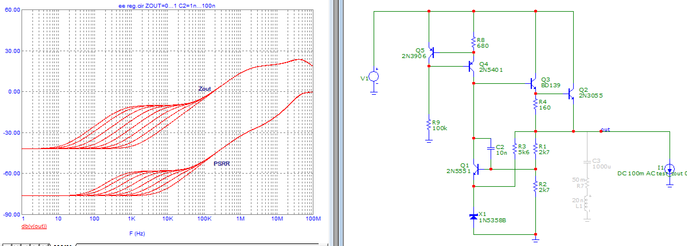
I used 2N5551 as error amplifier since it has higher voltage rating than 2N3904. PSRR is measured by setting an AC value of 1 on the input voltage source, and output impedance by setting an AC value of 1 on the output current source. Compensation cap is stepped.

Replacing the bias source (R1+R2) with a constant current source gives better PSRR and output impedance at low frequency. If this is for an audio amp, and the amp needs a regulated supply which is quite unusual, then this could mean the amp has bad PSRR. So having higher PSRR in the regulator could mean less hum in the output.

enter image description here

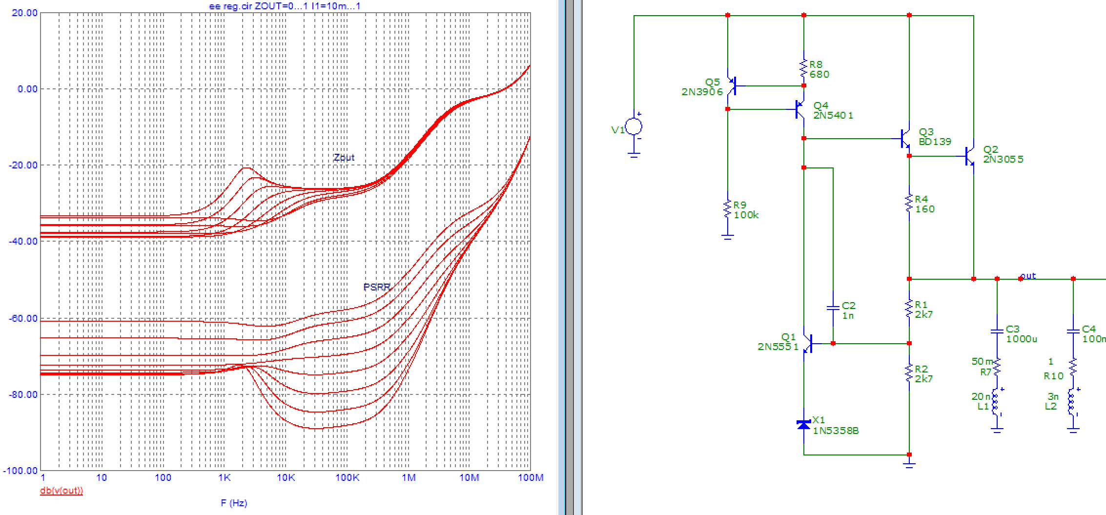
A compensation cap value of 1nF seems alright, the original 100nF seems way too large. Now adding the output cap, 50 mOhm seems a decent ESR for a 1000µF cap... Stepping output current:

enter image description here

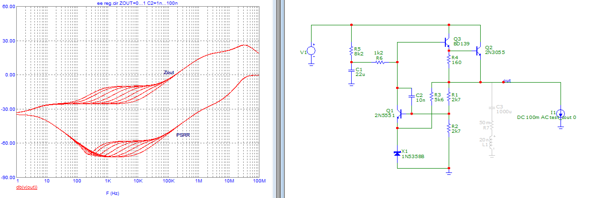
Zout depends on output current because Q3's transconductance also does. Q3 is also off at very low current. Assuming this powers an amp, it should burn at least 10mA idle, so I'm not going below that. There's a bump around 2kHz that I don't like. One solution to remove it would be to increase C3 to 4700µF which is ridiculous, or use a higher ESR cap.

\$\endgroup\$
5
  • \$\begingroup\$ Thanks a lot! That seems to more-or-less match my expectation. What transistor models did you use for simulation? I tried to find models matching the original parts, but maybe it's better to use generic/ideal parts? \$\endgroup\$
    – Michel
    Commented Jan 8, 2022 at 12:36
  • \$\begingroup\$ I just used 2N3904 and BD139. Maybe it failed because the models were wrong... \$\endgroup\$
    – bobflux
    Commented Jan 8, 2022 at 12:43
  • \$\begingroup\$ Using 2n3904 and bd139 models it's a bit better but still fishy, I think the zener is not modeled correctly? The voltage across it is 35.7-37.2, which does not seem right to me! No wonder it's not regulating in the simulator :) \$\endgroup\$
    – Michel
    Commented Jan 8, 2022 at 12:51
  • \$\begingroup\$ Thank you for the very detailed analysis! It's good to know that there's nothing wrong with the circuit: I did not know whether to doubt my reverse-engineering or my simulation, but the problem is definitely in the simulation. For some reason I still can't get the zener to work, so I'll focus on just modeling a zener to get that right. Regardig the compensation cap, it's marked with the numbers "400" and "4700" only, so I just put in ... something :') Question: I see you omitted the bridge etc, what kind of input voltage waveform are you using? \$\endgroup\$
    – Michel
    Commented Jan 8, 2022 at 19:24
  • 1
    \$\begingroup\$ If you have a problem with the zener model, you could try a different one, maybe from the BZX series. I'm using microcap simulator which is now free. I think "4700" means 470pF, that's much closer to the 1nF this sim indicates. I used 50V DC as input with an AC value of 1V, so output voltage gives PSRR directly without having to divide by 1V. \$\endgroup\$
    – bobflux
    Commented Jan 8, 2022 at 20:33

Your Answer

By clicking “Post Your Answer”, you agree to our terms of service and acknowledge you have read our privacy policy.

Not the answer you're looking for? Browse other questions tagged or ask your own question.