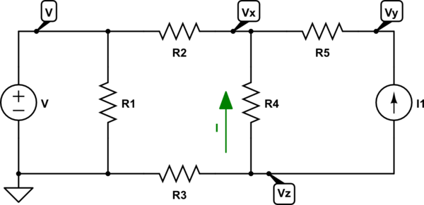
There's a nice schematic editor on this site. You should use it:

simulate this circuit – Schematic created using CircuitLab
I've labeled the nodes above and made a choice about which one I decided to call \$0\:\textrm{V}\$. You really only need to know the values for \$V_X\$, \$V_Z\$, and \$R_4\$ to figure out the current, \$I\$, using the obvious equation for the given arrow direction, \$I=\frac{V_Z-V_X}{R_4}\$. \$V_Y\$ isn't needed (though you could include it.) So you only need to solve the following:
$$\begin{align*}
\frac{V_X}{R_2}+\frac{V_X}{R_4} &= \frac{V}{R_2}+\frac{V_Z}{R_4} + I_1\\\\ \frac{V_Z}{R_3}+\frac{V_Z}{R_4}+I_1 &= \frac{V_X}{R_4}
\end{align*}$$
In matrix form, it's:
$$\begin{align*}
V_X\cdot\left(\frac{1}{R_2}+\frac{1}{R_4}\right)+V_Z\cdot\frac{-1}{R_4}&=\frac{V}{R_2}+I_1\\\\V_X\cdot\frac{-1}{R_4}+V_Z\cdot\left(\frac{1}{R_3}+\frac{1}{R_4}\right)&=-I_1
\end{align*}$$
And you can either solve that symbolically or numerically, if you have values handy. With the values in hand, you can then figure out \$I\$.
A symbolic solution could be done in the following way. Multiply equation 1 by \$R_2\vert\vert R_4\$:
$$\begin{align*}
V_X\cdot 1+V_Z\cdot\frac{-\left(R_2\vert\vert R_4\right)}{R_4}&=\left(R_2\vert\vert R_4\right)\cdot\left(\frac{V}{R_2}+I_1\right)
\\\\
V_X\cdot\frac{-1}{R_4}+V_Z\cdot\left(\frac{1}{R_3}+\frac{1}{R_4}\right)&=-I_1
\end{align*}$$
Now, zero out \$V_X\$ in the second equation by adding to it the first equation multiplied by \$\frac{1}{R_4}\$:
$$\begin{align*}
V_X\cdot 1+V_Z\cdot\frac{-\left(R_2\vert\vert R_4\right)}{R_4}&=\left(R_2\vert\vert R_4\right)\cdot\left(\frac{V}{R_2}+I_1\right)
\\\\
V_X\cdot 0+V_Z\cdot\left(\frac{1}{R_3}+\frac{1}{R_4}-\frac{\left(R_2\vert\vert R_4\right)}{R_4^2}\right)&=-I_1+\frac{R_2\vert\vert R_4}{R_4}\cdot\left(\frac{V}{R_2}+I_1\right)
\end{align*}$$
Divide the second equation so that \$V_Z\$ is multiplied by 1:
$$\begin{align*}
V_X\cdot 1+V_Z\cdot\frac{-\left(R_2\vert\vert R_4\right)}{R_4}&=\left(R_2\vert\vert R_4\right)\cdot\left(\frac{V}{R_2}+I_1\right)
\\\\
V_X\cdot 0+V_Z\cdot 1&=\frac{-I_1+\frac{R_2\vert\vert R_4}{R_4}\cdot\left(\frac{V}{R_2}+I_1\right)}{\frac{1}{R_3}+\frac{1}{R_4}-\frac{\left(R_2\vert\vert R_4\right)}{R_4^2}}
\end{align*}$$
Now, multiply the second equation by \$\frac{R_2\vert\vert R_4}{R_4}\$ and add that into the first equation to zero out \$V_Z\$:
$$\begin{align*}
V_X&=\left(R_2\vert\vert R_4\right)\cdot\left(\frac{V}{R_2}+I_1\right)+\frac{R_2\vert\vert R_4}{R_4}\cdot V_Z
\\\\
&=\left(R_2\vert\vert R_4\right)\cdot\left[\frac{V}{R_2}+\frac{V_Z}{R_4}+I_1\right]
\\\\
V_Z&=\frac{-I_1\cdot R_4+\left(R_2\vert\vert R_4\right)\cdot\left(\frac{V}{R_2}+I_1\right)}{1+\frac{R_4}{R_3}-\frac{\left(R_2\vert\vert R_4\right)}{R_4}}
\end{align*}$$
Remember that \$I=\frac{V_Z-V_X}{R_4}\$, so if you are really wanting to have fun with algebra, plug in the values and simplify further.


