1
\$\begingroup\$

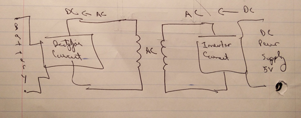
I am trying to build a wireless battery charger. Below is a rough idea of what I want to achieve.

Basic Idea for Wireless Charger

Currently I am having trouble with the inverter circuit that is shown below.

GreatScott! H-Bridge Inverter Circuit

I understand that this inverter circuit is converting DC to AC by using an H-Bridge configuration with the use of MOSFETS, MOSFET Drivers, timer IC and Inverting IC.

My question is how do I calculate the AC Voltage produced by this inverter if I am to supply 12V DC and set the working frequency to 100khz for wireless power transmission through a litz pancake coil?

I know that regular inverters convert 12VDC to 240 VAC with the use of a transformer. I have tried looking at the 74HC4049N inverting IC datasheet and am unable to identify the outputting AC voltage.

I need to know how much AC is produced in order to correctly build a Diode Bridge rectifying circuit on the battery side.

Any Help will be sincerely appreciated.

\$\endgroup\$
2
  • 1
    \$\begingroup\$ Whatever you supply as VCC is impressed (positive and negative) across the coil. So the coil will see 2 X VCC or 24V peak to peak voltage if VCC=12V. \$\endgroup\$
    – John D
    Commented Feb 13, 2017 at 20:25
  • \$\begingroup\$ The output voltage at connector X3 should be a little less than 24Vp-p as John D has said. It seems like you are mixing up the different meanings of "inverter". You are trying to build an inverter that converts power at DC voltage to usually higher AC voltage. 74HC4049 is a logic inverter that invert the logic state from input to output. Two completely different things. \$\endgroup\$
    – rioraxe
    Commented Feb 14, 2017 at 1:55

1 Answer 1

1
\$\begingroup\$

The power inverter schematic you've posted uses U1 and U2 to drive Q1 to Q4, to put whatever supply voltage there is, in this case 12v, alternately forwards and backwards across the load. As the load is differentially driven, I prefer to call this +/- 12v. Some folks like to call it 24 v peak to peak, which while correct I find can cause confusion.

The logic inverter HC4049 is a low power device, completely unrelated to a power inverter, so you won't find any joy in its datasheet.

Your overall system diagram is labelled oddly. Your battery is followed by (what appears to be labelled) a 'Rectifier Circuit'. You would use a high frequency power inverter at this point, to drive the transformer you've marked 'AC'. After the transformer comes a box labelled '... Ah! the penny drops, I've just noticed the arrow.

Your overall system diagram is drawn right to left, sredaer (nertsew tsom dna) hsilgnE fo tou lleh eht sesufnoc hcihw <-. Please draw diagrams so the major signal flow is left to right, even if you've put a direction arrow on it.

\$\endgroup\$

Your Answer

By clicking “Post Your Answer”, you agree to our terms of service and acknowledge you have read our privacy policy.

Not the answer you're looking for? Browse other questions tagged or ask your own question.