0
\$\begingroup\$

I would like to make a small board with a simple MCU that just repeatedly sends a message via a modem on one end of a power line wire (14awg or so). On the other end will be a similar device for reading that message. The only requirement is not interfering with/cutting the wire or isolation in any way. There will not be access to a plug or any way to directly tap into the line like PLC home networks do. The device will be powered from an external source (3.3 or 5V).

I've done some reading on this topic and the ST7540 seems to be a good option, in my case I would not need to filter out the 50/60Hz because there would be no electricity on the line. I am mainly uncertain about the induction, possibly using some kind of coil around the power line. What I basically want is to use the power line wire as an antenna between two modules (approx 3m or 10ft apart). I can't use full wireless (315MHz for example) for various reasons.

What is the best way to inductively transmit data (only one direction is needed, tx to rx) over a power wire that has no voltage/current and what kind of parts would be required? Are there modems specifically made for something like this? I remember reading about something similar being used in under-water applications in the past.

Hypothetical example: There's a 2-lead mains wire permanently plugged into an outlet in my room. The wire leads to the next room and it powers a lamp with a switch (relay). I can't go into the next room. I want to induce a modulated signal into the mains line by means of a transceiver/MCU while the lamp is off (no voltage/current in the mains wire), the signal goes through the mains wire, which acts as an antenna. There's a receiver/MCU on the mains line in the other room, which reads the signal inductively and turns on the relay, lighting the lamp. I do not want to physically manipulate the mains wires in any way, but also can't use a regular RF link (I know this could easily be done wirelessly).

\$\endgroup\$
2
  • \$\begingroup\$ maximintegrated.com/en/products/comms/… \$\endgroup\$
    – User323693
    Commented Feb 18, 2017 at 3:57
  • 1
    \$\begingroup\$ Can you please justify why a non contacting method is ruled out and why radio is also ruled out. I will also draw to your attention that you have received some good answers to earlier questions and you have not formally accepted any. This lack of action will put some folk off giving help. \$\endgroup\$
    – Andy aka
    Commented Feb 18, 2017 at 9:18

1 Answer 1

2
\$\begingroup\$

Consider PPM....pulse position modulation.

Couple pairs of spikes into the hot-wire. For ZERO, place the spikes 5 uS apart. For ONE, place the spikes 10uS apart.

Send the bits every 100uS.

Or, to have a very narrow-band datalink, so you can narrow-band filter to reject more noise, for ZERO, send +spike,+spike, For ONE, send +spike,-spike.

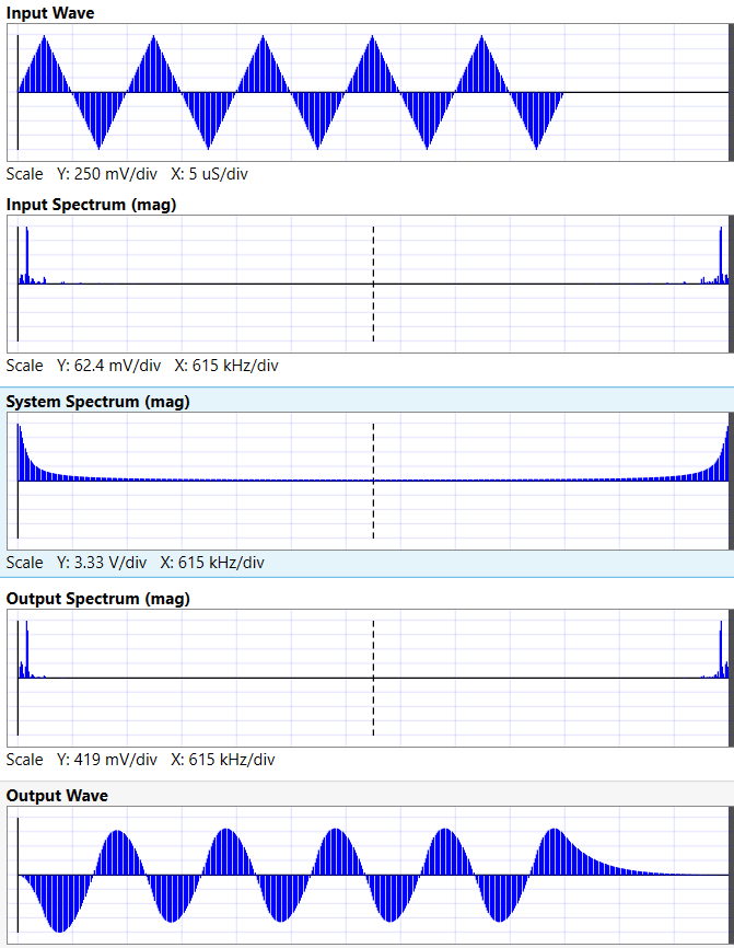
Examine some Fourier signals and pick your spacing and modulation. Here are useful waveforms and spectra from Signal Wave Explorer. I used the JBStage (canned example) with trapezoidal input (50%, 50%, no plateaus)

enter image description here

Notice how narrow-band (centered at 200KHz) the output spectrum is.

By the way, the powerline can easily kill you. Are you thinking about transformers wrapped about the HOT wire?

\$\endgroup\$
5
  • \$\begingroup\$ Yes, this is why I want to induce the signal without physically tapping into the wire by means of a ferrite for example. 1] It is dangerous, 2] It would void the warranty of the device, 3] it would have to somehow be isolated anyways due to the voltage differences. Like wireless charging, but sending a modulated signal. During the time of sending the signal, there will not be any voltage on the mains line. I will add an example to the question. \$\endgroup\$
    – Fid
    Commented Feb 18, 2017 at 4:19
  • \$\begingroup\$ Send long or short tone bursts. To achieve narrow bandwidth for noise reduction, monitor a long period of time, and then correlate with inphase and with quadrature patterns in the receiver. \$\endgroup\$ Commented Feb 18, 2017 at 4:29
  • \$\begingroup\$ I think the military used something similar for public alarms, atleast back in the day. What I'm unsure about is roughly what parts would be used, eg. ferrite beads? Would I have to amplify the signal for it to travel 10ft if using 3.3V signal bursts? \$\endgroup\$
    – Fid
    Commented Feb 18, 2017 at 4:38
  • \$\begingroup\$ Consider 10pF (copper foil wrapped around 10cm of the power cable) at 100,000Hz. 1pf at 1GHz is 159 ohms. 1pF at 1MHz is 159,000 ohms. 10pF at 100,000Hz is 159,000 ohms. If you provide 1.59 volts peak (3.18 volts PP), you get 10uA coupled into the power line. What voltage to expect? \$\endgroup\$ Commented Feb 18, 2017 at 7:03
  • \$\begingroup\$ 10 meters of wire is approximately 10uH, which looks like 6.3 ohms at 100,000Hz. With 10uA injected, you'll get 63 microVolts at 100,000Hz at the receiver; using sort of voltage divider as model for the datalink. You'll need to filter and amplify that for reliable data movement. Have you tried coupling from a MCU PWM output, thru 10pF, into a floating power extension cord? Use a scope probe to any wire of the cord, and you'll see some level of spikes on the transmitted edges. That's an idea of what's possible. \$\endgroup\$ Commented Feb 18, 2017 at 7:08

Your Answer

By clicking “Post Your Answer”, you agree to our terms of service and acknowledge you have read our privacy policy.

Not the answer you're looking for? Browse other questions tagged or ask your own question.