I think I've phrased the title correctly, although happy to be corrected. For some reason I'm having a huge problem wrapping my head around the use of ground in low voltage (e.g. 3.3V / 5V) circuits. I've read this answer a few times and have a better understanding, however still have this unanswered question.
As far as I understand, in the UK, if I were to plug in my DC power adapter into a socket the voltage is 230Vac, referenced, at some point, to the actual earth. Inside the adapter, a SMPS circuit using transformers, regulators and filters outputs a 5V DC voltage, for instance. What is that 5V referenced to? Is the negative line of the DC output tied to the AC earth?
If I were to take two different power adapters, hypothetically, I assume it would be possible for one of the two to have a potential of 100V on the +ve line and 95V on the -ve line? That provides a 5V potential difference, therefore working the same as the other that had a potential of 5V on the +ve line and 0V on the -ve line. What would happen if the -ve lines of these were tied together in a circuit (i.e. a common ground)?
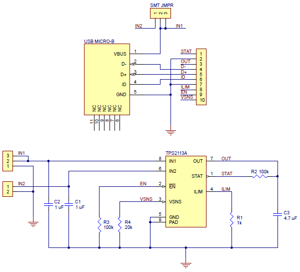
My questions stems from the desire to use an auto switching power mux such as the TPS2113A. The grounds from the two supplies must be tied together, but what if they're at a different potential? An example circuit from Pololu is below.

