1
\$\begingroup\$

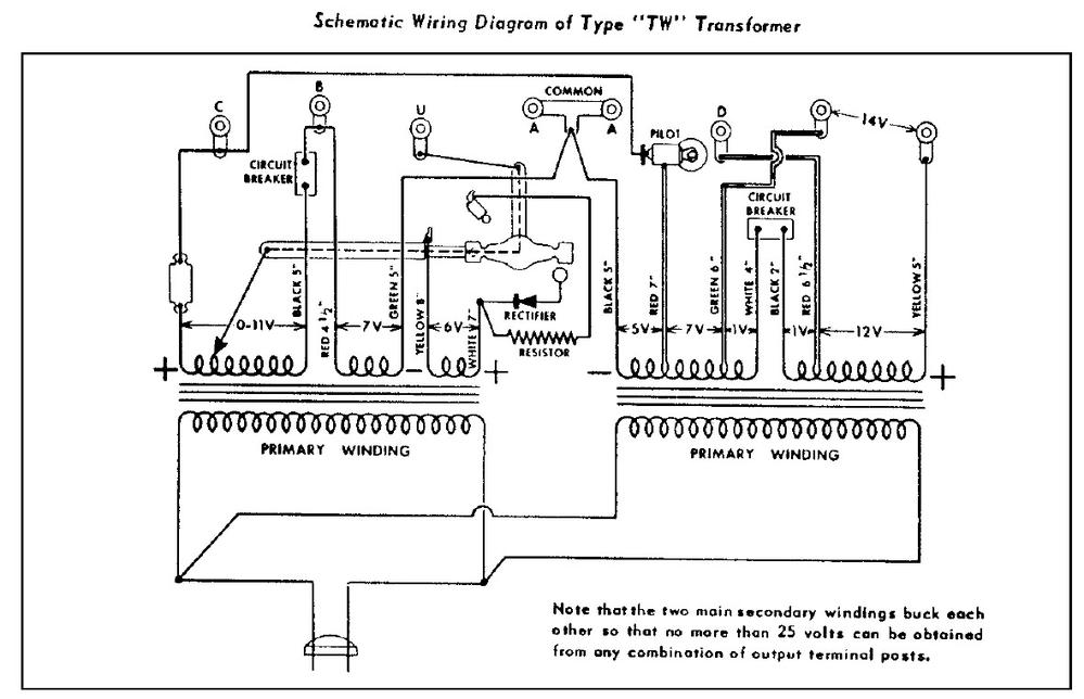
Image from http://www.trainfacts.com

Lionel is a company that makes model railroad sets and parts. I have some of their "O-gauge" products and want to learn more about how the transformers work.

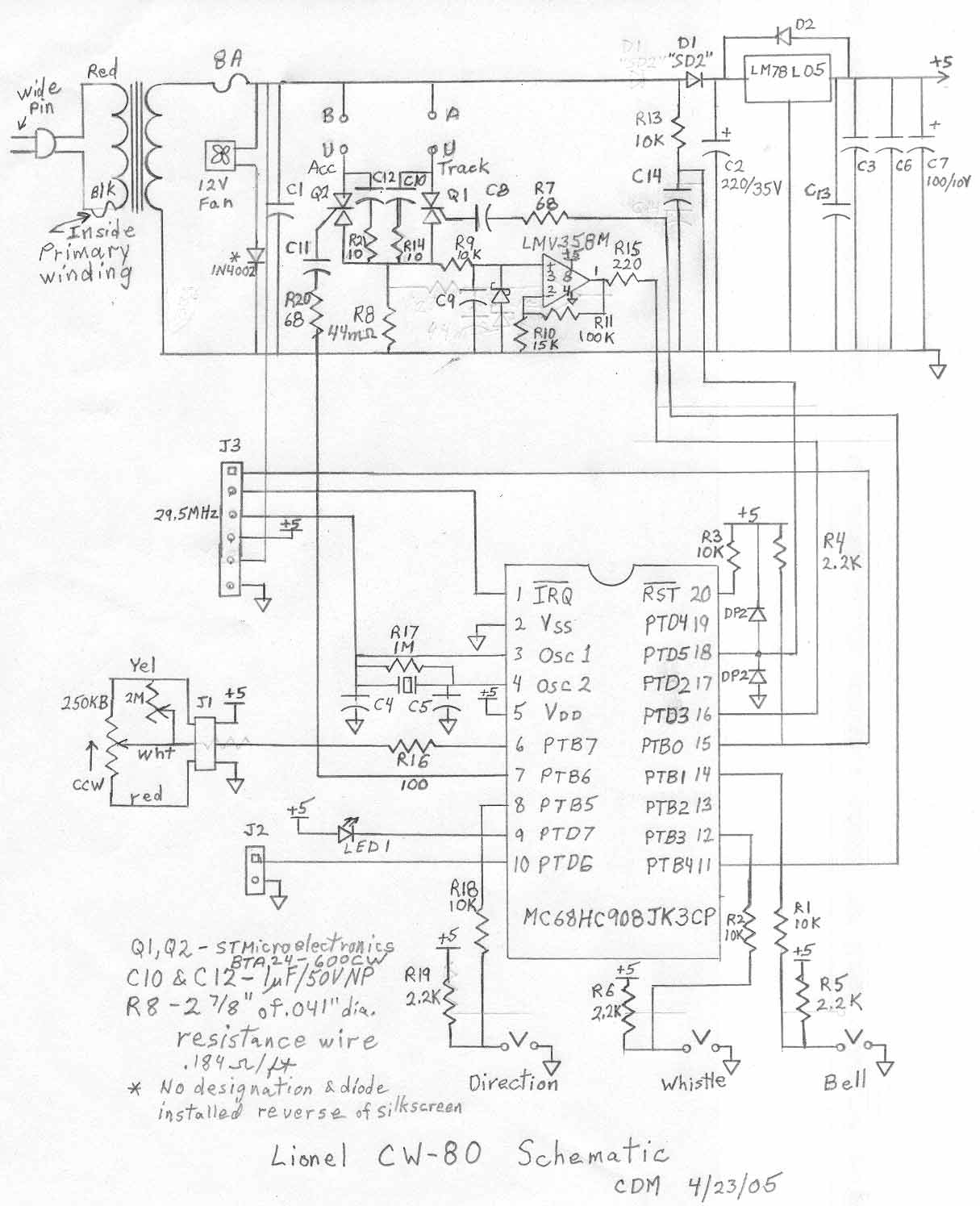
Above is a schematic of the transformer by a train enthusiast. No schematics are available from Lionel.

The transformers are actually 'controllers', as they do more than just transform the voltage. They also provide three different "activation" buttons:

1) Direction - a button press switches the locomotive's direction with each button press, Forward to Neutral to Reverse to Neutral to Reverse, etc.

2) Bell - a button press turns the bell sound ON. A second press turns the bell OFF. This happens because a button press "adds DC current to the output" which "changes the shape of the AC sine wave". (from sine wave shape to 'shark-fin' shape)

3) Whistle - momentary switch that makes the whistle sound while the button is pressed down. This also happens because a button press "adds DC current to the output" which "changes the shape of the AC sine wave". But this sine wave mod is different from button (2)s sine wave change.

I am not interested in the electronic function of the (1) direction control. The direction is also controlled by reducing voltage to 0 via the voltage control handle. The button seems to be redundant control of voltage supply, and it's probably just a momentary kill switch. In any event, that's not what I'm keen to learn about.

What I am really curious about is what the other buttons do electronically and electrically.

I already know that pressing either (2) or (3) adds DC current to an AC signal. Or at least that's what I think I know from what I can Google about it. And that DC current overlaid on the AC current is what distorts the AC sine wave.

It is somehow the shape of the sine wave that activates the sounds, or DC on the tracks that activates the sounds, or some combination of the two. I have read much that is unclear or seems contradictory out in Google-land.

I also have read that when the sound control buttons are pressed, the 18v AC gets some 'boost' somehow to allow for consistent delivery of power to the locomotive's motor (thus not causing the locomotive to slow down every time you sound the whistle).

But I don't really understand what's happening here... It's all done via a processor on a chip on the circuit board inside the transformer and I am WAY past my limits of comprehension.

So...

Can someone please give me a step-by-step explanation of what actually happens as you press (2) or (3)?

An explanation comprehendible by someone with only very limited knowledge of electronics?

Thanks.

\$\endgroup\$
7
  • \$\begingroup\$ I don't think this is an on topic question here. We do need a circuit diagram so we know what's actually happening, otherwise it would just be guesses. \$\endgroup\$
    – Bradman175
    Commented May 17, 2017 at 2:12
  • \$\begingroup\$ I believe the control schemes you described date prior to the invention of transistors when only vacuum tubes were used for electronic circuits. Electrical and electro-mechanical schemes were used for the functions described. Brief voltage increase pulses were used to activate solenoids that were designed to be inactive when the normal voltage was applied but activated only by the pulses. The solenoids were used in relays or stepping relays to activate functions. The direction control activated a set of contacts that reversed the motor or switched between 2 motors. Lionel site might have more. \$\endgroup\$
    – user80875
    Commented May 17, 2017 at 2:19
  • \$\begingroup\$ My comment is based on my recollection of what I saw on a Lionel site and my interpretation of that. Since I think the question is off topic here, I won't try to research it and interpret it further. \$\endgroup\$
    – user80875
    Commented May 17, 2017 at 2:23
  • \$\begingroup\$ @Bradman175 I added the only drawing of the transformer I could find. \$\endgroup\$
    – 111936
    Commented May 17, 2017 at 2:35
  • \$\begingroup\$ @CharlesCowie Lionel started to use sounds way back pre-solid-state, true. But the transformer I am asking about is a c.2013 model that uses a processor and solid state electronics to control the signal to the tracks. Also, if this question is misplaced I don't understand why - I am asking about what happens when you activate an electronic device. Figured the electrical engineering section is where people who would know these things will be! You EEs actually design this sort of thing, so are the relevant experts? \$\endgroup\$
    – 111936
    Commented May 17, 2017 at 2:40

2 Answers 2

4
\$\begingroup\$

I didn't know much about this- as a kid I had a Lionel set, but it had a single variac type control lever. It's not too hard to find out though.

The unit you show has two phase-controlled outputs using triacs Q1/Q2. One is to feed accessories (a variable AC voltage that I assume the operator sets to control brightness of stationary lights and such like), and the other feeds the track (a variable AC voltage with momentary DC offset of positive or negative polarity) added- and momentary interruption function.

enter image description here

Normally on a phase control such as an old-school lamp dimmer, it is desirable to maintain symmetry between the positive and negative half cycles. In the case of Lionel's scheme, an asymmetry can deliberately be introduced to actuate one of two devices on the locomotive depending on the polarity of the resulting DC content. There are two possible polarities of offset so two devices can be controlled (whistle and bell).

The aforementioned asymmetry is introduced entirely by timing the trigger pulses to the triac. The model in question apparently works only with 60Hz power only- so the timing of the trigger pulses is a delay from the zero crossing of almost nothing up to 1/120 second or about 8.3 millisecond. The MCU operates with a 1MHz crystal clock, so accurate timing is particularly easy.

Zero crossing is detected by the MCU (microcontroller) via R13/C14 and is clamped by the diodes before being fed to an MCU input port pin.

The MCU triggers the triacs via pulses produced on pins 7 and 11. Total current of both accessories and track (positive half-cycles only) is monitored via the shunt resistor R8 and the LMV358 op-amp. It can measure peak currents of up to about 14A. The Schottky diode on pin 3 clamps the input so it can't go too far below ground. The main 250K\$\Omega\$ (B = linear taper) pot is fed to an MCU analog-to-digital converter input pin.

In order to get a DC component one of the pulses has to be later than the other. In order to maintain roughly constant AC voltage to the locomotive motor the timing must be adjusted for both pulses- one retarded and one advanced- which will only be possible if the speed is sufficiently less than 100% (or greater than 0%, which is probably not an issue).

I believe reversal is achieved by interrupting power to the locomotive momentarily so as to toggle the direction. Again, this is timing of the pulses to one of the triacs- interrupting them for a short time.

Anyway, the magic is virtually all in the firmware of the MCU, though anyone with appropriate microcontroller skills and an oscilloscope could duplicate this functionality.

References:

  1. CW-80 Manual

  2. US Patent 2155343 Remote Control System, Method and Apparatus 1939

\$\endgroup\$
2
  • \$\begingroup\$ Hey @SpehroPefhany - Wow, awesome explanation. I had to look up what some of the components you named do, but now I get what is happening. Followup question if you feel like answering: Is it possible to build a standalone circuit for each button without using a MCU? Eg- the 110v to 18v step-down transformer supplies two separate non-MCU "wave modifiers"? \$\endgroup\$
    – 111936
    Commented May 19, 2017 at 0:05
  • \$\begingroup\$ @Nixt Sure- I think they used a separate winding on the transformer at one point. Rather than a custom transformer you could use a 2nd transformer, for example. But to actually design such circuit would require some practical information on typical currents and voltages. The scheme was patented in 1929 so for the first 50+ years it would have been done without MCUs. \$\endgroup\$ Commented May 19, 2017 at 12:27
0
\$\begingroup\$

The original transformer was a tap changing under load (TCUL) transformer which altered the number of coils o the secondary side. This type of transformer is the predominant transformer used for power system distribution which you see at many substations. They are also called on-line tap changing (OLTC). The "bump" to engage the whistle or change direction was the least expensive method, at that time, to send a command. The more recent tap changing is accomplished by power electronic devices which are known as Flexible AC Transmission equipment. The most recent rendition is an AC-DC-AC device to add a phase shift through power electronics to control the flow on an individual transmission line. The other approach to control model trains was to inject a harmonic signal on top of the AC signal which could then be filtered to activate a device. The original power line carrier (PLC) injection was done by a tube based circuit. The concept of PLC is still used in power systems and in many home today. The complexity has increased thanks to ICs and MCUs.enter image description here

\$\endgroup\$

Your Answer

By clicking “Post Your Answer”, you agree to our terms of service and acknowledge you have read our privacy policy.

Not the answer you're looking for? Browse other questions tagged or ask your own question.