The various LPC microcontroller chips have a boot mode that accepts serial communication and writes the received program to Flash. I want to make a PCB with and LPC1114 that must be programmed in circuit, with only minimal interface circuitry on the PCB. Is there a standard connector for supplying the required signals (GND, RxD, TxD, Reset, BootModeEnable)?
-
2\$\begingroup\$ There are standard connectors for JTAG and SWD, but there is no standard connector for program loading via a serial connection. \$\endgroup\$– Leon HellerCommented Apr 24, 2012 at 19:15
-
\$\begingroup\$ For lack of a standard, is there some connector that is often used? Or even a single board that has such a connector?? \$\endgroup\$– Wouter van OoijenCommented Apr 24, 2012 at 19:21
-
\$\begingroup\$ Just use a header with three pins - Gnd, Tx and Rx. \$\endgroup\$– Leon HellerCommented Apr 24, 2012 at 20:22
-
\$\begingroup\$ For 'hands off' one or two extra pins are needed: reset and BootModeEnable (could be combined at the cost of some extra circuitry). \$\endgroup\$– Wouter van OoijenCommented Apr 25, 2012 at 6:40
6 Answers
I use Sparkfun's USB to UART board. I bring out UART0, reset and isp to headers. I connect reset and isp to ground with jumpers, then use FlashMagic. This only seems to work right if I also power the device from USB, so the grounds are common.
Sparkfun's board:
-
\$\begingroup\$ You don't need to take power from usb to establish common ground, it is enough to tie the grounds together. \$\endgroup\$ Commented Mar 12, 2013 at 1:13
If you set up a connector to be compatible with the header version of a low voltage FTDI USB serial cable, you have the option of not needing to contract for the manufacture of custom cables.
You can drive the boot mode off a status line and couple the reset to that with a cap (think I might have used a transistor as an inverter when I did this with an ST part). Then deselecting and reselecting the boot mode will reset the chip and prepare it for download.
-
\$\begingroup\$ I considered that approach, but I'd rather stick to the more or less standard two-handshake-lines-approach. That leaves the option open to command a non-bootload reset, and saves a few components on the target board. \$\endgroup\$ Commented Dec 21, 2012 at 15:02
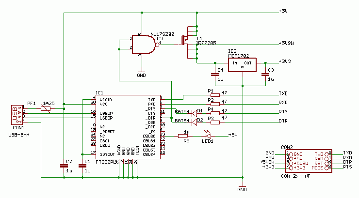
Since no standard seemed to exist, I made my own choice: a 2x4 right-angled pin header for the target board, and a ditto female connector for the 'programmer' board. The programmer has an FT232RL or similar, a 5V->3.3V regulator, and a switch to disable the power to the target board (required to force the target chip into programming mode when the reset pin has been re-purposed as GPIO).
 connector pinout

 programmer ('dongle') circuit diagram

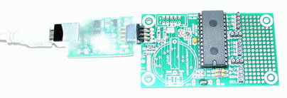
Programmer with a minimally populated LPC1114 target board.
I use lpc21isp as programming tool on the PC (open source, easily compiled for Windows or Linux), but I had to add one line to the code because the way it starts the application after a download (jump to the start of the code) does not work for a Cortex.
I did not work with LPC1114 before but take a look at the below address. On the left, you will see a link to a schematic file...
-
\$\begingroup\$ This board has the serial interface hardware (in this case: max232 chip, but could be an FT232RL or something else) on the PCB, so there is no connector that carries the signals I want to interface. \$\endgroup\$ Commented Apr 24, 2012 at 18:21
-
\$\begingroup\$ On the second page, there is the JTAG interface. You have to use a JTAG adapter on the PC side, but on the PCB, there is no additional hardware like RS232... \$\endgroup\$ Commented Apr 24, 2012 at 18:34
-
\$\begingroup\$ I want to use the serial interface, not JTAG. Too complicated, too much signal lines. \$\endgroup\$ Commented Apr 24, 2012 at 18:45
-
\$\begingroup\$ SWD only requires two or three signals. You get debugging, which is very useful. \$\endgroup\$ Commented Apr 24, 2012 at 19:19
-
2\$\begingroup\$ True, but at the cost of a more complex interface at the PC side. (And I seldom use a debugger, even if I have one available) \$\endgroup\$ Commented Apr 24, 2012 at 19:22
Im actually building something with the same micro. I just picked up one of these: http://ics.nxp.com/lpcxpresso/ for ~$20 from digikey, cut off the "target" side of the board, and wired up a custom connector on the "LPC link" side to work with my programming header. The CodeRed made environment is annoying since its Eclipse based (I loathe Eclipse) but it works in Windows, Linux, and maybe Mac. They have instructions for all of the command line programs to work with the LPC Link interface.
I have an environment set up in linux to just run make dl and it will initialize the link, program it, and enable security bits, all via USB and the SWD connections to the LCP1114. Can even be used for debug provided that you don't reuse one of the SWD signals.
It isn't serial like you are looking for, but it works like a charm.
-
1\$\begingroup\$ I know the lpcexpresso's, I have 1114, 1343, 1769 and the baseboard. Nice stuff (although I ditched both the IDE and the LPC link in disgust), but not suited for what I want. My PCB will be 20 x 50 mm max. \$\endgroup\$ Commented Apr 24, 2012 at 19:54
-
\$\begingroup\$ @WoutervanOoijen, I use vim and have all of the tools set up to run via command line. My board is a bit bigger but it should work just the same. In past when I have done small projects like that I made the programming pins come out to largish pads, and then rig up a custom jig to connect those up via spring loaded pins and hold it in place. I don't really know of any off the shelf solutions for a "common/standard" connector to connect to your PCB. \$\endgroup\$ Commented Apr 24, 2012 at 20:52
If you want serial programming with the standard connector (meaning RS232) why don't you implement normal UART (MAX3232 or something) with standard DB9 male connect on the LPC side? Than you simply use the extender (male to female) DB9 cable towards PC (or use serial to usb cable if you PC does not have serial port). In any case, put a female DB9 on your PLC board, and you never ever have to manufacture your serial cable :-). Don't forget to wire pins properly, extender cables are straight (1-1, 2-2, ... 9-9).
If the space on the board was issue (not enough room for DB9) then you can provide 2 x 5 pin header only.
Of course, you could also use spare MAX3232 level shifters to force your board into reset / boot mode like I did on my NXP/AT89C51Rx2 based board also using Flashmagic. Same principle, teh Falshmagic takes control over the boot entry via serial line.
All that said, I would go with SWD / JTAG and had debugging at my disposal.
-
\$\begingroup\$ (comment some 6 years later...) I don't want to use the standard RS232 connector, that would be a waste of circuitry (on both sides). I want minimal circuitry at the target side (essentially 0). \$\endgroup\$ Commented Sep 22, 2019 at 17:53
