0
\$\begingroup\$

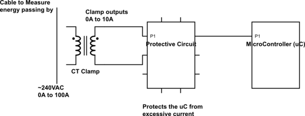
I am trying to make a very basic energy meter that is basically an Arduino (a random microcontroller) attached to a Current Transformer (CT) that I can clamp around an electric cable in an electric board (one for each phase).

For what I've understand I will have a function that, according to each CT specification, will translate me the current Arduino is measuring in one end of the CT, with the current the CT is measuring in the other end (the electric cable I want to measure).

I can estimate energy consumption over time if I assume that the voltage is constant (240VAC for eg.). However this is not always true and I want to be able to measure voltage as well, using this same CT.

How can I do that with a CT? Does the CT voltage outputted to Arduino vary in a way that I can correlate with the voltage on the measured cable?

The connection diagram is the following:
schematic

simulate this circuit – Schematic created using CircuitLab

\$\endgroup\$
2
  • 1
    \$\begingroup\$ You can draw a schematic using the embedded editor, will probably be clearer than your ASCII art :P \$\endgroup\$
    – Wesley Lee
    Commented May 22, 2017 at 13:02
  • \$\begingroup\$ Oh cool. Thanks, didn't know about that new feature. \$\endgroup\$
    – nemewsys
    Commented May 22, 2017 at 13:09

2 Answers 2

7
\$\begingroup\$

A CT clamp will measure current taken by the load from the supply it is being fed. So, if the supply voltage is 240 VAC and the load is 240 ohms then the CT will produce a signal indicative of 1 amp RMS flowing.

If the supply were 200 VAC and the load were 200 ohms, the CT would also indicate 1 amp RMS flowing.

In other words, no, the CT doesn't have any facility to indicate what the supply voltage is nor what the load is. You cannot measure power or energy without both a current and voltage measurement device.

\$\endgroup\$
10
  • \$\begingroup\$ How can these guys do it with just a CT clamp? panpwr.com They can provide both current and voltage. \$\endgroup\$
    – nemewsys
    Commented May 22, 2017 at 13:10
  • \$\begingroup\$ You'll have to provide a working link to the product you refer to. \$\endgroup\$
    – Andy aka
    Commented May 22, 2017 at 13:13
  • \$\begingroup\$ Their sensors are these ones: panpwr.com/sensors-and-communications \$\endgroup\$
    – nemewsys
    Commented May 22, 2017 at 13:14
  • 1
    \$\begingroup\$ They are very evasive about what the current sensors do except that they clearly do state they are current sensors. Why don't you ask them? \$\endgroup\$
    – Andy aka
    Commented May 22, 2017 at 13:20
  • 1
    \$\begingroup\$ Ask them about accuracy and ability to deal with current harmonics as seen when bridge rectifiers are used directly inside appliances. I will say this: there only needs to be one common voltage reference measurement transmitted cyclically to all current sensors to be able to compute power - maybe they are doing something along these lines or maybe they are just BS! \$\endgroup\$
    – Andy aka
    Commented May 22, 2017 at 13:33
2
\$\begingroup\$

This works if your current is with no phase shift. Reactive loads render this unusable.

The solution: Add another wire through the clamp, having multiple turns. Have a relay or solid state switch that connects a known resistive load through the extra wire and check, how much the current measurement result grows.

Let your extra load be R and it's wire has N turns in the clamp. Let the switching the R on cause current increase = Ix.

The voltage is (R *Ix) / N

\$\endgroup\$

Your Answer

By clicking “Post Your Answer”, you agree to our terms of service and acknowledge you have read our privacy policy.

Not the answer you're looking for? Browse other questions tagged or ask your own question.