1
\$\begingroup\$

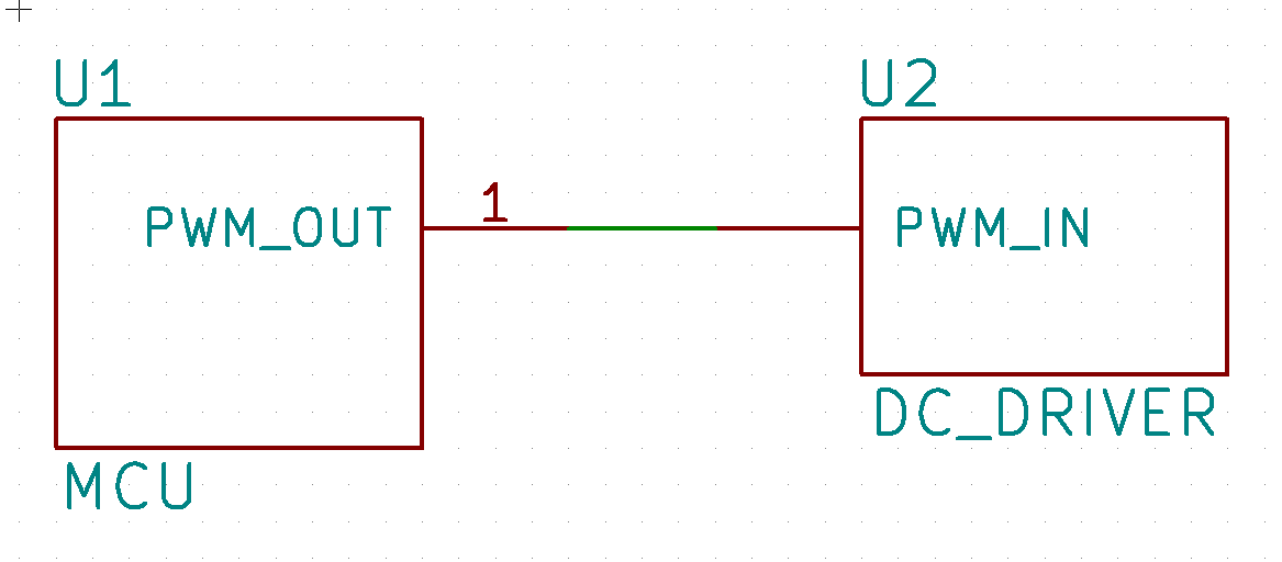
I wired a DC motor driver with a MCU, just like the following simplified figure. Simple.

enter image description here

The PWM output frequency is 2kHz and it has 3.3V logic. It works very well as I expected. However, I have one minor problem with this: the MCU has a floating output on reset so the DC motor spins so fast until the MCU initialize the PWM out pin. I have a couple of questions about this problem.

  1. A solution I can come up with is to add a pull-down resistor between the PWM line and GND. Is that a right solution, or are there other ways to prevent the floating output on reset?

  2. If yes, what's the preferable resistance for the pull-down resistor??

Thank you in advance.

EDIT: The host MCU is STM32F446RET and the motor driver IC is MAX14871. The PWM output in in question is PA8.

\$\endgroup\$
3
  • \$\begingroup\$ Can you edit your question to specify the components and I can edit my answer into something more meaningful. Thanks :-) \$\endgroup\$
    – TonyM
    Commented May 27, 2017 at 22:34
  • 1
    \$\begingroup\$ @TonyM Sure. I added it. Thanks for answering the question :) \$\endgroup\$
    – Bumsik Kim
    Commented May 27, 2017 at 22:42
  • \$\begingroup\$ @immibis, that's often true as you say. But the acceptable range of values are always calculated for the application (see my answer below), you never just drop in a 'probably' value without datasheet check/calculation to verify. Right? \$\endgroup\$
    – TonyM
    Commented May 28, 2017 at 8:00

2 Answers 2

5
\$\begingroup\$

As you've correctly identified, during power-up, MCU reset and your configuration software running and finishing, your I/O pin will be in its initial state.

The actual initial state depends on your particular MCU. Some configure their pins as high-impedance inputs, some (MCS-51) put them as inputs with pull-up resistors.

Your STM32F446RET has an input leakage current of +/-3 uA. When configured as an output, it can deliver +/-25 mA although there's some conditions on that.

The MAX14871 motor driver PWM pin has input leakage current of +/-1 uA and recognises 0.8 V or less as a logic low.

A pull-down resistor will do the job fine. The value has to be low enough to conduct the MCU and driver input leakage currents while developing a small-enough voltage drop across itself to be seen as an 'off' by the driver. The value has to be high enough to not load the MCU so much that it can't deliver the 'on' voltage to the driver.

From R=V/I, you can see that a 25 K pull-down resistor would leave PWM at 0.1 V with 4 uA flowing through it. So you can use 10 K and still draw less than 330 uA from the MCU output when it drives high.

\$\endgroup\$
2
\$\begingroup\$

Yes, a pull down would make sense. Id start by guessing 10k, but you ought to be able to work out from the data sheets what input current you should expect.

\$\endgroup\$

Your Answer

By clicking “Post Your Answer”, you agree to our terms of service and acknowledge you have read our privacy policy.

Not the answer you're looking for? Browse other questions tagged or ask your own question.