0
\$\begingroup\$

I'm doing a project in which I want to turn on an LED with different instensity depending on the input of a sensor. For now, I'm simulating the sensor with a potentiometer.

I'm using an EK-TM4C123GXl launchpad. I connect the 'fake' sensor input to an ADC input (through an op. amp.), then I vary the PWM pulse width depending on the value read from ADC.

I have tested that the PWM output powers the LED and varies its lightness depending on the current pulse width, having the ADC input is disconnected. However, as soon as I connect the ADC input, the PWM output goes to 0V (just after generating a 'spike' in the LED, I can see it because it brights a lot for an instant).

I have 'solved' the problem by placing a resistor between the PWM output and the LED. However, I don't understand at all why this happens. I have though that the PWM pulse is finding a way to ground through the MCU internals and the ADC input, I still don't see how can a resistor (R5) fix that.

The schematics is below (VCC is a 9V battery):

EDIT

Previous schematics was wrong, here is the correct one: enter image description here
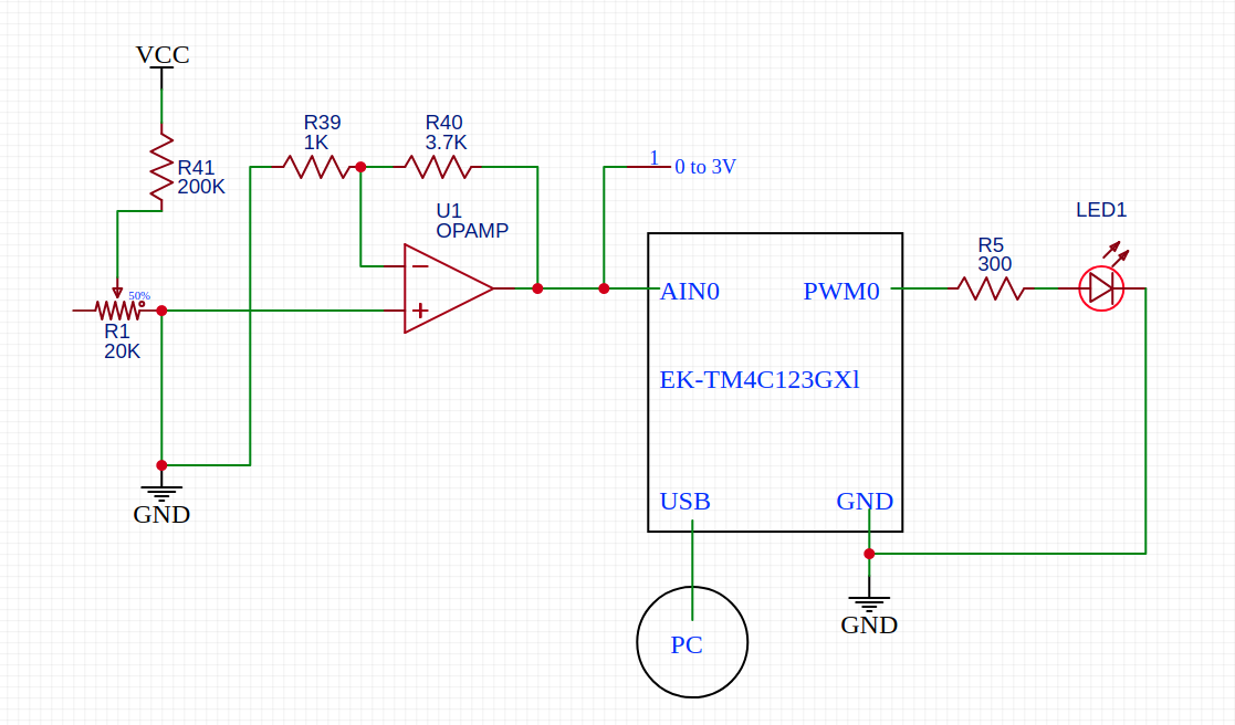
The resistor R5 is the one that prevents the PWM output to go ground, that is, if I remove it and connect the LED directly to PWM0 it remains off and its anode at 0V.

How can this be happening? Can this be related with the input leakage current?

Pins configuration:

  • ADC input pin: input, analog, no pull down resistor.
  • PWM output pin: output, digital, no pull/down resistor, no open drain, 2mA drive strength.

Notes:

  • VCC is a 9V battery
  • I use a potentiometer and an op. amp. because the potentiometer is supposed to fake what will be an actual light sensor. The op. amp. is there for the shake of making the simulation more realistic, since I pretend to use it in the final design.
  • I have tested that the op. amp. output is between 0 and ~3V (never more than 3)
  • I connect the board GND pins to the same ground as all the other ICs.
  • The MCU is powered by the USB port, which is connected to my PC.
  • I don't provide the code because it's very long and I have tested several times that it's correct (I insist, everything works fine if R5 is present)
  • All impedances are given in ohms.
  • The op. amp. is non-inverting output (I remark this just in case I have made a mistake with it)
  • I have read that the LED should always by protected by a current-limiting resistor. I didn't put it in first place because I misunderstood what the pin's drive strength is, but the point is I want to know how can the absence of R5 can cause PWM0 to go to 0V.
\$\endgroup\$
1
  • \$\begingroup\$ I don’t know which port is used but there are open collector 220R RGB ports and maybe you had the LED to 3.3V so it could not go to ground with a different CMOS 25 Ohm 3.3V driver to an LED which is between 10 and 15 Ohms at 20 mA Rs at 2.1V for Red \$\endgroup\$
    – D.A.S.
    Commented Mar 30, 2021 at 22:30

4 Answers 4

2
\$\begingroup\$

enter image description here

Figure 1. Original circuit.

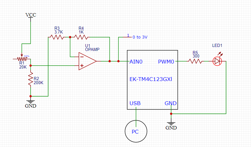
R1 is not wired as a potentiometer. It's wired as a variable resistor or 'rheostat'. If you move the wiper to the right the op-amp will see 5 V. If you move it to the left the op-amp will see \$ \frac {200k}{20k + 200k}5 = 4.55 \ \text V \$.

Meanwhile your op-amp has a gain of \$ 1 + \frac {R_4}{R_3} = 1 + \frac 1 {3.7} = 1.27 \$ so at minimum input voltage the output is trying to get to 5.77 V but, fortunately, I suspect, is limited by U1's supply voltage. Since you're only getting 3 V maximum it probably means you are not using a rail to rail output op-amp. Check the datasheet to see what the maximum output voltage swing is.

I have read that the LED should always by protected by a current-limiting resistor. ... but the point is I want to know how can the absence of R5 can cause PWM0 to go to 0V.
If you don't add R5 the PWM output will be overloaded. The voltage will max out at about the rated forward voltage, Vf, of the LED and at the maximum current that the microcontroller can give. This is neither good for the micro or the LED. Use a current limiting resistor.

\$\endgroup\$
2
  • \$\begingroup\$ VCC is 9V but never mind, the explanation with 5V is perfectly fine. \$\endgroup\$
    – Martel
    Commented Mar 30, 2021 at 22:58
  • \$\begingroup\$ And the op. amp. is badly wired (my bad), actually R3 and R4 should be one in the place of the other. And the pot. as well, it is the opposite: first R2 and then R1, so the input voltage for the op amp is much lower. Sorry I will update the schematics as soon as I can \$\endgroup\$
    – Martel
    Commented Mar 30, 2021 at 23:00
1
\$\begingroup\$

Measure the current that the led draws without the R5 (with and without AINT0 connected). That's what I would do, if I were you, check what really is going on there,.

I think it is more than "2mA drive strength" This 2mA must be the EK-TM4C123GXl pin's maximum value, which you should be taking care of (this means that the EK-TM4C123GXl can give more than 2mA, but you must limit it to 2mA).

Where did you see this 2mA limit? I could not see it in the datasheet, its also pretty big datasheet, it could take me some time

My guess: When the EK-TM4C123GXl gives 5V (pwm or not) to the led, if you do not have the R5 connected there, this 5V output will be a short to GND.

\$\endgroup\$
1
  • \$\begingroup\$ The drive strength options are 2, 4 and 8 mA (don't remember if that 4 is actually 6, but the 2 and 8 options are correct for sure) \$\endgroup\$
    – Martel
    Commented Mar 30, 2021 at 22:49
1
\$\begingroup\$

Additionally, depending on if you aren't concerned about cost, you can always add a buffer to help maintain signal integrity, this should protect the PWM from potentially being pulled to ground if its being attenuated significantly.

\$\endgroup\$
0
\$\begingroup\$

I have done some more tests. Specifically, I have tested the circuit without R5 and powering the MCU through its VBUS pin, with 3.3V. All works.

I still can get overcurrent to the LED if I turn the rheostat all to the right (10mA while the maximum ratings for the LED specifies 7mA).

In summary, the whole problem came from powering part of the circuit (sensor, op. amp.) with a 9V battery while powering the MCU with the PC USB. I have no idea how can this affect the PWM output though.

\$\endgroup\$

Your Answer

By clicking “Post Your Answer”, you agree to our terms of service and acknowledge you have read our privacy policy.

Not the answer you're looking for? Browse other questions tagged or ask your own question.