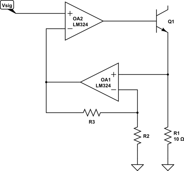
I designed a small circuit to drive LEDs with a classical constant current source (transistor and opamp). Then I realized, that a colleague using this circuit might do something wrong and tries to drive a super high current through the LEDs (SW problems we all now). The LEDs would die. To avoid this I want to limit the input signal (the voltage at the non-inverting input). What do you think about this protection circuitry?
-
\$\begingroup\$ How is the colleague (or software) controlling the input signal? Why not just make sure the scaling from input (DAC or pot) to the op-amp input is reasonable? \$\endgroup\$– The PhotonCommented Jun 18, 2017 at 17:58
-
\$\begingroup\$ Building on @ThePhoton good comment, you would make the DAC full-scale output voltage produce the largest LED current that the application requires and that the LED can continuously handle with no significant difficulty or degradation. The DAC should not be capable of getting the LED damaged, unless the application absolutely requires it. \$\endgroup\$– TonyMCommented Jun 18, 2017 at 18:17
-
\$\begingroup\$ My idea is to put the LED driver on its own PCB and maybe someone else is at some point developing a digital board, which is completely independent from this one. I mean it is always kind of obvious, that you should not go beyond 30 mA with 5 mm UV LEDS, but people still burn up LEDs. \$\endgroup\$– m3x1m0mCommented Jun 18, 2017 at 22:58
-
\$\begingroup\$ Could you just put a zener on vsig to clamp it to some maximum voltage? Seems like the most straightforward way. \$\endgroup\$– John MeachamCommented Jun 19, 2017 at 10:52
1 Answer
Per The Photon's comment, you might find something like this simpler

simulate this circuit – Schematic created using CircuitLab
where R3 and R2 are chosen to give the desired current at the maximum input voltage which your colleagues can produce. This, of course, means that you'll have to supply a higher input voltage to produce the same current level, but that may or may not be a problem. Certainly, providing voltages as low as you do seems a bit unusual.
-
\$\begingroup\$ I like this circuit a lot. I am a bit unsure, but I think in my case it does not make sense, since I have been not specific enough about the application targeted. There is only one stage shown above. "In reality" this will be 64 stages to drive 256 LEDs. So if I understood the circuit correctly this would mean, that I need 64 additional opamps, which is too expensive. Please correct me if this is wrong. \$\endgroup\$– m3x1m0mCommented Jun 18, 2017 at 22:53
-
\$\begingroup\$ @m3x1m0m - You can get LM324s new for less than 20 cents apiece, and 1% resistors for about 10 cents apiece. Since you would need 64 channels, this means an increase of about 8 dollars. Since this will replace an LM324, 7 resistors, 2 transistors and an LED, it will save you at least 50 dollars. \$\endgroup\$ Commented Jun 19, 2017 at 14:18
-
\$\begingroup\$ The over current protection you only need once as the current through all stages shall be the same. \$\endgroup\$– m3x1m0mCommented Jun 26, 2017 at 9:34
-
\$\begingroup\$ @m3x1m0m Nope - at a minimum you have to replicate R2, R3 and Q2 to each driver channel. \$\endgroup\$ Commented Jun 26, 2017 at 13:47

