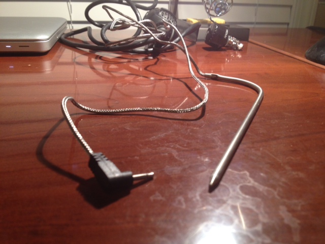
As Nathan mentions, it looks like a meat thermometer probe. Those probes are inexpensive, so it's probably a thermistor, or possibly a thermocouple, and not anything more exotic like a platinum RTD or a temperature sensing diode. If the resistance between the tip and sleeve of the connector is over a few ohms, it's almost certainly a thermistor. Otherwise it's either a thermocouple or an unusually low resistance thermistor.
If it's a thermistor, you'll need to use it as one half of a voltage divider. Since the change in resistance is usually only a few percent/degree C it's often necessary to rescale the value using an op-amp circuit before analog-to-digital conversion. To pick the gain and offset of that circuit, you need to consider the range of temperatures you wish to measure, and the input and output ranges of the op-amp.
For converting resistance to temperature, instead of Steinhart-Hart, you might be better off using the B parameter equation:
\$\frac{1}{T} = \frac{1}{T_0} + \frac{1}{B}ln(\frac{R}{R_0})\$
Note that \$T\$ and \$T_0\$ are absolute temperatures (Rankine or Kelvin). One of the calibration points will be \$R_0\$ and \$T_0\$, and you can find \$B\$ based on the other calibration point either algebraically or numerically (goal seek in Excel). \$B\$ tends to be around 3000 Kelvin for most NTC thermistors.
If it's a thermocouple, you need a high input impedance differential amplifier. Thermocouples create a small voltage and can't supply much current. For accuracy, you'll also need to compensate for the themocouple voltage created where it plugs into your device. Measuring the thermocouple signal is a bit more involved than a thermistor, but not out of the range of DIY. Many DMMs have a mode to read thermocouples, which could help verify that is indeed what you have.

