I'm a hobbiest with litte resources for parts, so I'm short on things I can use.
Therefore I'm trying to rescue an old amplifier's case and use it for a different project. The potentiometer on the front has got me stuck though. It's a slider style, with some weird trickery.
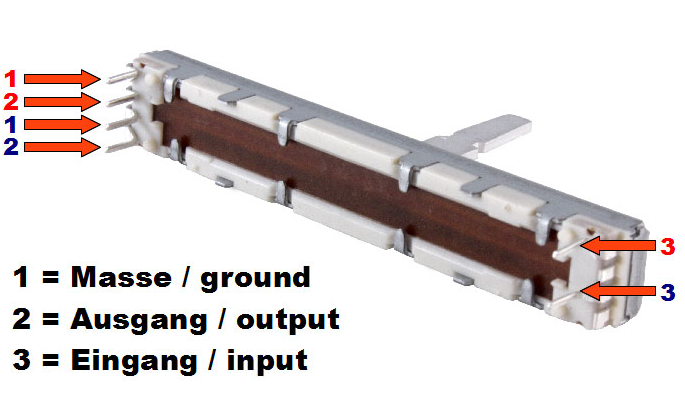
It has 6 pins. Four on the left, two on the right. Across the four on the right I get a linear taper but never much change in resistance. Across the far-apart pins (the ones coincidentally or not also in a parallel line geometrically speaking) give me a really weird audio-taper. The issue is: The frequency response is really low (cuts off high frequencies) and the sound isn't dimming how it's supposed to.
The pot changes resistance from 192k to 2.2 ish k. It never goes down fully. I'm not sure if I need to replace this with a linear taper (as I like Linear better for sound myself as a personal preference) or if someone can help me get this working correctly.
I read about the voltage divider stuff and I'm not sure how to implement that as I do not understand how this potentiometer works.
Either way, if I can replace the pot to a nicer newer one (although the old one is of a brand like Porsche is to cars and mitutoyo to measuring instruments) and get it working correctly. THIS has had me STUMBLED for SO long!
Edit: Thanks Transistor for your input! here's some of the things you requested.
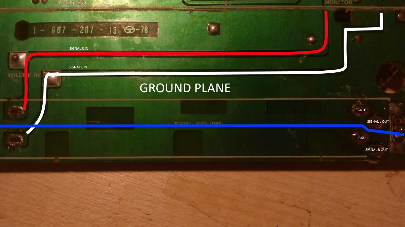
Here you can see the original layout. I may just be seeing something over the head however. Note: Any measurements with probes ACROSS the blue line are NOT connected. The both sides of the blue line are seemingly two different potentiometers.
I will measure the resistances in the morning. It's a quarter to five here.
Oh and voltage divider: If I ground half the signal isn't that kinda like a small short circuit?
PS: If you'd like any more explanation on something specific or any pictures, feel free to let me know. I'm all about that helping.


