0
\$\begingroup\$

I have this voltage regulator from this supplier and the exact model name is given as: "LM317T/NOPB".

I plan to use this circuit to power a windwane's potentiometer which is around 10 kΩ:

enter image description here

As you see I want to set the excitation voltage for the vane pot to around 9 or 10 V where the op-amp will be supplied directly from a 12 V switch-mode power supply. For this purpose I will use an LM317 to obtain 9 or 10 V for the vane excitation, so I will set the LM317 for 9 or 10 VDC.

I will mount the vane in a box around 50 m high which will stay there for at least 3 months.

Since I will use a linear voltage regulator I decided to find out whether I need a heatsink.

I have encountered two challenges which I put here as questions:

  1. In the datasheet, when I check the thermal resistances, I can't figure out which model I should use:
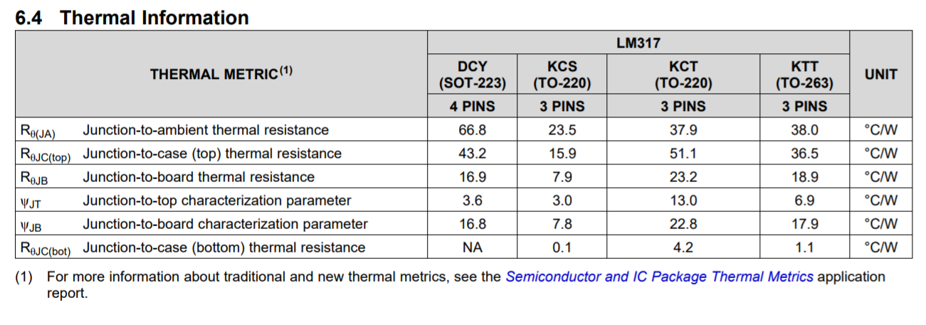
    enter image description here

    Mine is T0-220, but in the datasheet there are two types namely KCT and KCS, but my model is "LM317T/NOPB", and on it it is written "LM317T +P". So should I use the thermal resistance for KCT or KCS?

  2. Here is how I calculate the ΔT:
    ΔT = θJA × P
    In my case:
    P = V2 / R = 102 / 10000 = 0.01 W

    But for junction to ambient temperature I used to use the following:

    Junction to Ambient = Junction to Case + Case to Ambient

    But in the datasheet there is no Case to Ambient but there is Junction to Ambient. Does "Junction to Ambient" already include "Case to Ambient"? Should I in my case only use Junction to Ambient? If so, in my case ΔT becomes like 4°C, and I conclude I don't need heatsink. Did I calculate correctly and does the duration (three months) matter when it comes to using a heatsink?

\$\endgroup\$
6
  • \$\begingroup\$ With a 10k pot, the LM317 only needs to source 1 mA. So its power consumption is only 2 mW. You're way over-thinking this. \$\endgroup\$
    – The Photon
    Commented Sep 9, 2017 at 21:18
  • \$\begingroup\$ If the part you bought actually has the National Semi logo on it, that means its been sitting around in RS's stockroom for at least 5 years. If you were using enough power to actually care about the answer to this question, it would be better to buy new parts so you can get a datasheet that actually corresponds to your part. \$\endgroup\$
    – The Photon
    Commented Sep 9, 2017 at 21:26
  • \$\begingroup\$ Is my using thermal resistance using only "Junction to ambient" (θJA) is enough ? \$\endgroup\$
    – user1245
    Commented Sep 9, 2017 at 21:29
  • \$\begingroup\$ And where in the datasheet I can find out the minimum input voltage needed for this regulator to output 10V? Thanks \$\endgroup\$
    – user1245
    Commented Sep 9, 2017 at 21:31
  • 1
    \$\begingroup\$ If you have multiple questions, ask them with multiple posts. But search first to see if the question has already been asked. (Hint: the term to search for is "drop-out voltage") \$\endgroup\$
    – The Photon
    Commented Sep 9, 2017 at 21:32

1 Answer 1

1
\$\begingroup\$

You have calculated the power dissipated in the wind gauge - what you need to know is the power dissipated in the LM317. The wind vane will draw 1 mA, and you have 3 volts across the LM317, for a power dissipation of 3 mW due to the load. However, the LM317 requires a minimum load current of 5 mA for proper operation - the voltage-setting resistors are usually selected to draw that current.

With 1 mA for the wind gauge, and 5 mA for the LM317 operation, the LM317 will dissipate about 6 mW - no need for any heat sink at such a low power. You could use a TO-92 packaged LM317 without concern.

\$\endgroup\$
3
  • \$\begingroup\$ Oh thanks I understand now. But couple of things 1-) Where did you find 5mA in the datasheet? In datasheet at 6.3 in Recommended Operating Conditions min output current is 10mA 2-) So as thermal resistance using only "Junction to ambient" (θJA) is enough right? thanks in advance \$\endgroup\$
    – user1245
    Commented Sep 9, 2017 at 21:13
  • \$\begingroup\$ The TI datasheet shows "Minimum load current to maintain regulation" with a typical value of 3.5 mA, and maximum of 10 mA. I got the 5 mA figure out of my head - but it is reasonable. My answer doesn't really answer the calculation question, but does show the power dissipation is so low that there's no need to worry about heatsinking. \$\endgroup\$ Commented Sep 9, 2017 at 21:50
  • \$\begingroup\$ The circuit has the voltage-setting resistors missing, also the important input and output capacitors are missing, all are shown in the datasheet. \$\endgroup\$
    – Audioguru
    Commented May 30, 2021 at 23:48

Your Answer

By clicking “Post Your Answer”, you agree to our terms of service and acknowledge you have read our privacy policy.

Not the answer you're looking for? Browse other questions tagged or ask your own question.