3
\$\begingroup\$

I'm currently using a linear current source to drive a single LED as in here. In my case (following the notation in the link), VDD is directly connected to a single cell lithium polymer battery, i.e. Vcc = 3.0 ~ 4.2 V. For the transistor and MOSFET, I am using MMBT3904LT3G(Digikey link) and 2N7002P,235(Digikey link), respectively. Rs is set to 2.2 Ohms. My desired current is approximately 250 mA.

Here is the circuit diagram from the site:
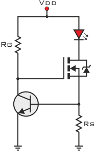
linear current source

The problem is that there is so much heat dissipated it is hard to touch the PCB board. There are 3 LEDs (and corresponding circuits) in total on a 50 mm x 50 mm PCB (FR-4, 1.6 mm thickness). I am measuring 565 mV (which actually keeps dropping as the PCB heats up) across R2 and a voltage drop of 2.14 V across the LED at Vcc = 4.2 V. I am guessing that most of the heat is generated from Q2, since it has to drop the rest of the voltage which is approximately 1.5 V.

I have considered using a step-down switching regulator to drop the battery voltage to around 3 V, which I certainly think will help the problem. I have also looked on Digikey to find dedicated ICs such as this one. However, both require an inductor that I have heard to be expensive. There also seems to be charge pumps that I am not sure will be effective in my case (LED forward voltage is always lower than the battery voltage).

What would be the best way to go? In the end, I am looking for a cost-effective solution, but now open to any suggestions. And could you clarify whether charge pump LED drivers (such as this) will be effective for my case.

\$\endgroup\$
2
  • 2
    \$\begingroup\$ You haven't told us the LED current you want. That IC is rated at 200mA according to the link. \$\endgroup\$
    – user16324
    Commented Nov 16, 2017 at 9:42
  • \$\begingroup\$ @BrianDrummond I have edited the post to include the desired current. \$\endgroup\$
    – Jann
    Commented Nov 16, 2017 at 10:09

3 Answers 3

2
\$\begingroup\$

If it is "hard to touch the pc board", then by a common rule of thumb (or finger) your board is running at about 60 C. That is generally considered the "must let go" temperature. While that is indeed pretty hot, it's within the tolerances of the parts you're using. If you put the pc board in a small enclosure it will get hotter still. Air flow (cool air) is your friend.

As for reducing the temperature, you are out of luck. Your LED drops 2.15 volts at .25 amps. A Vc of 4.2 volts means that Rs and your FET will collectively drop (4.2 - 2.15) volts, or about 2.05. 2.05 volts times .25 amps gives .5 watts. 3 times that is 1.5 watts. And yes, I'd expect 1.5 watts over a 4 square inch pcb to get pretty hot. Rs is dissipating 1/4 watt, and your FET is dissipating 3/8 of a watt, which is right up at its limit.

ANY linear regulator doing your job will dissipate the same amount of power. The only question is how you deal with it. If you want to stick with your circuit, you'll need to learn about heatsinks.

\$\endgroup\$
0
\$\begingroup\$

Assuming I am looking at the right circuit, which you should have reposted here so people do not have to go back and forward....

Also assuming you wanted 0.25A per LED and they can handle that.

Your choice for Q2 is way undersized at 350mW you need at least a 1W part if not a 2W and a heat-sink would not hurt. The 2N7002P is also a MOSFET. I do not see any MOSFET circuits in your link. So this whole answer may be bogus. A MOSFET may cause this circuit to oscillate, and is not buying you anything.

R2 also needs to be at least a quarter Watt, which will be at 20C above ambient, a half Watt would be cooler.

The LEDs themselves, at half a watt each, are your worst offenders and also need special treatment to get rid of heat.

As for reducing heat.

With a linear solution at that range of voltages in, you don't get a choice, you need to dissipate @3W, which is not that bad for a two inch square. You can better manage the heat, but the wattage is what it is. A switching driver would be better for this high a current, and the inductors are not as expensive as you might think, not compared to a ton of heat-sink stuff. There is nothing you can do reduce the LED heat generation though, other than run them dimmer.

Anyhow, fix Q2 first to a larger NPN part that wont get so hot temperature wise.

\$\endgroup\$
8
  • \$\begingroup\$ Oh, I hadn't noticed that the MOSFET was way undersized. Should change it to a larger part as you have pointed out. Still, I cannot understand why a NPN will be better than a MOSFET in this case. As you have said, wattage is wattage. Or is it just better in terms of stability of the circuit? \$\endgroup\$
    – Jann
    Commented Nov 16, 2017 at 11:11
  • 1
    \$\begingroup\$ @Jann remember this is a linear circuit, the MOSFET is not saturated so does not add any benefits. Instead you have added significant capacitances to the equation which, with the addition of any significant impedance from wiring, and the sharper threshold, may make the thing oscillate. Horses for courses. \$\endgroup\$
    – Trevor_G
    Commented Nov 16, 2017 at 11:18
  • \$\begingroup\$ Why half W for R2?. Voltage is about 0.6 V current 250 mA . Quarter Watt will be fine. \$\endgroup\$
    – RoyC
    Commented Nov 16, 2017 at 14:40
  • \$\begingroup\$ @RoyC Normally that would be true. However, since that resistor is controlling the current level, you want it to stay as close to ambient, and the expected resistance, as you can. \$\endgroup\$
    – Trevor_G
    Commented Nov 16, 2017 at 14:42
  • \$\begingroup\$ Q2 should be a BJT as you say but is dissipating a maximum of (4.2-.6-2.1)V x 250 mA = 375 mW granted a 350 mW device is undersized but 2 W? \$\endgroup\$
    – RoyC
    Commented Nov 16, 2017 at 14:47
0
\$\begingroup\$

You could possibly reduce the current by using a lower wavelength red.
1 Watt of radiated flux at a wavelength of 625nm will produce 180 lumens. At a wavelength of 620nm would produce 260 lumens (45% increase).

Red LEDs range from 30 lumens to over 100 lumens per watt. Using a high efficiency red LED (100+ lumens per watt) will reduce the required current.

Cree 623nm XPEBRD-L1-0000-00902 = 109 lm/W
OSRAM 626nm GR CSHPM1.23-JUKQ-1 = 101 lm/W

Lumiled Luxeon Color C 629nm L1C1-RED1000000000 = 53 lm/W


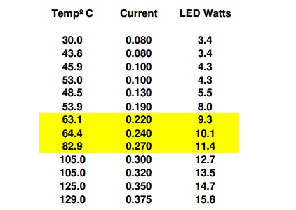
At 250mA the LEDs are going to heat the board beyond 50°C (touchable but uncomfortable) without significant thermal management.

I measured the temperature of a string of 16 white LEDs spaced 0.75" on a 0.7" wide PCB with no heatsink. The temperature was measured on the bottom side under an LED.

enter image description here


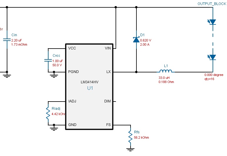
This is a simple low cost very efficient driver circuit.

enter image description here


Inductor

small low cost inductor with low DCR Colicraft MSS1038


Driver

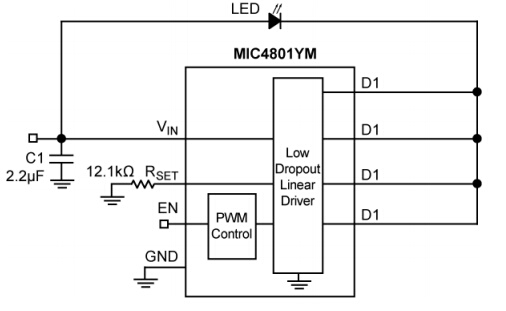
This is an efficient Low Dropout Linear Driver

enter image description here


Adjustable Constant Current Regulator & LED Driver

150mA - 350mA CC Regulator On Semi NSI50150ADT4G

\$\endgroup\$
1
  • \$\begingroup\$ Lowering the LED Vf will cause the other components to dissipate more heat, since the current will remain (approximately) the same. \$\endgroup\$ Commented Jul 9, 2022 at 13:43

Your Answer

By clicking “Post Your Answer”, you agree to our terms of service and acknowledge you have read our privacy policy.

Not the answer you're looking for? Browse other questions tagged or ask your own question.