0
\$\begingroup\$

For a little project of mine (FPV OSD for Quadcopter Camera) I need to detect every time the signal voltage goes negative. The Signal I get is NTSC. Here each line sync is marked by the voltage going to about -0.3V. The OSD itself will be realized using an ATTiny, which can't read negative voltages. Also, the ADC on the ATTiny is by far too slow to detect that short line sync time. For this to work I will need to use a digital interrupt.

So I nees some kind of circuit, that detects every time the Voltage dips below 0V and turns that into a HIGH (>0.7V), while it stays LOW if the voltage is above 0V. This should work fast enough for NTSC (so should be able to work at at least a few megahertz).

I am basing this on an existing open source circuit that currently uses an LMH1980 (for line sync detection) together with an ATTiny13A (to render the actual OSD), which (the LMH1980) is comparatively expensive and bulky. I think it should be possible to replace the LMH1980 wih a cheaper and simpler circuit to detect negative voltages (=line syncs) and have the existing ATTiny do the then trivial work of detecting line and frame syncs.

I would prefer the solution to use only standard components and be as small and simple as possible.

Edit: One design constraint that I forgot to mention is that the solution should impact the video signal as little as possible to not introduce image artifacts, since the video singnal will also be sent over a video transmitter and viewed by the pilot.

\$\endgroup\$
8
  • \$\begingroup\$ "each line sync is marked by the voltage going to about -0.3V" - can you be a bit more specific? What is the sync pulse amplitude, and why are the pulses going below ground? \$\endgroup\$ Commented Nov 25, 2017 at 23:16
  • \$\begingroup\$ Do you have access to a negative voltage supply? \$\endgroup\$
    – pserra
    Commented Nov 25, 2017 at 23:23
  • \$\begingroup\$ @Bruce Abbott: That's the way NTSC works. Each line contains a continuous analog signal describing luminamce and color for that line. Each line is seperated from the next line by the signal going to about -0.3V for about 4-5 microseconds. I don't have control over that protocol since the device needs to work with existing cameras and video transmitters. \$\endgroup\$
    – Dakkaron
    Commented Nov 26, 2017 at 3:07
  • \$\begingroup\$ @pserra: I fear not so... \$\endgroup\$
    – Dakkaron
    Commented Nov 26, 2017 at 3:08
  • \$\begingroup\$ An NTSC video signal may be DC coupled or AC coupled. If it is DC coupled then the sync tips will most likely be at or above ground. If it is AC coupled then sync voltage will change according to average brightness of the image. AC coupled video needs 'DC restoration' to stabilize the sync voltage. \$\endgroup\$ Commented Nov 26, 2017 at 7:39

2 Answers 2

1
\$\begingroup\$

I am no video expert but I do understand the negative sync pulse and, as far as I can see, your understanding is correct too.

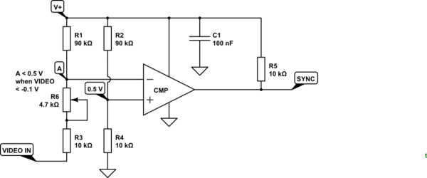
schematic

simulate this circuit – Schematic created using CircuitLab

Figure 1. A comparitor can be made to work on signals outside its rail-to-rail limits by use of potential dividers.

Comparators are better than op-amps for this type of job as they are designed to switch rail-to-rail whereas op-amps can take some time to recover when the output hits either rail.

How it works:

  • R2 and R4 set a reference voltage of 0.5 V.
  • With R6 at minimum resistance R1 and R3 would do the same and the comparitor would switch when the video signal crosses 0 V.
  • The resistor values chosen drop \$ \frac {5}{100k} = 50 \mathrm {mV/k} \$, To change the switching point to -0.2 V, therefore, we need to add about 4k to the negative leg. A 4k7 pot should give you enough adjustment to get reliable detection.
  • Since you want an output high when A goes low then A must connect to the '-' input.
  • Many comparators have open-collector outputs (check the one you've chosen) so R5 may be required if your micro's pull-up is not sufficient.
  • Check the specs of your chosen comparitor and make sure it can work with input signals as low as 0.5 V.
  • C1 is required to decouple the comparator from the supply.

The circuit will put a 5 V bias onto your video signal but with > 100k source impedance which the video driver should be able to handle. If this proves to be a problem you could scale up R1, 6 and 3 by a factor of ten. You could find out easily by connecting your video to +5 V through a 100k resistor.

Finally, 90k is an odd resistance value but I chose it just to make the maths easier. 100k will be fine and R2 / R4 will give \$ \frac {5}{11} \ \mathrm V \$ rather than \$ \frac {5}{10} \ \mathrm V \$.

\$\endgroup\$
1
  • \$\begingroup\$ @Dakkaron: Thanks for accepting my answer. Did it actually work? \$\endgroup\$
    – Transistor
    Commented Jan 23, 2018 at 19:19
1
\$\begingroup\$

Simplest is to use a Schmitt Trigger. You can find the details at Wikipedia using that name. You also find schematics there for transistors and Op-Amps. (I would use an Op-Amp). You also find the formulas there. There was a remark about negative voltage but you don't need that. If you take a resistor divider from e.g. a 3.3V supply and connect it to the sync, the voltage over the resistor will vary between 3.3 and about :-) 3.6V. For example, if you use two resistors in the ratio 3:7 your voltage swing will be ~200mV. Adjust your Schmitt trigger resistors to detect the difference between those voltages.

\$\endgroup\$
2
  • \$\begingroup\$ Thanks for the hint with the Schmidt Trigger, that seems to be exactly what I have been looking for. For the rest with the voltage division: I am a bit unclear on what you meant. In the NTSC-Signal only the negative parts are relevant, since voltage levels down to 0V are possible in the regular video signal as well. Only the part where the voltage goes below 0V is the vertical sync that I want to find. \$\endgroup\$
    – Dakkaron
    Commented Nov 26, 2017 at 7:38
  • \$\begingroup\$ One design constraint that I forgot to mention is that the solution should impact the video signal as little as possible to not introduce image artifacts, since the video singnal will also be sent over a video transmitter and viewed by the pilot. \$\endgroup\$
    – Dakkaron
    Commented Nov 26, 2017 at 7:42

Your Answer

By clicking “Post Your Answer”, you agree to our terms of service and acknowledge you have read our privacy policy.

Not the answer you're looking for? Browse other questions tagged or ask your own question.