4
\$\begingroup\$

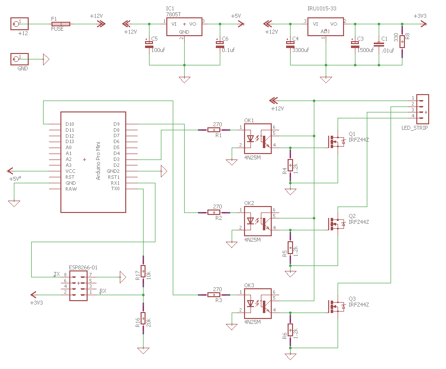
I have this circuit implemented on a prototype board.

Circuit

The 12v power source is a 4A switching power supply. This powers the 12v LED strip, the 7805 regulator for the Arduino, and the IRU1015-33 3.3v regulator for the ESP8266.

The led strip is a 5 meters 12v 30leds/meter RGB, controlled by PWM from the arduino.

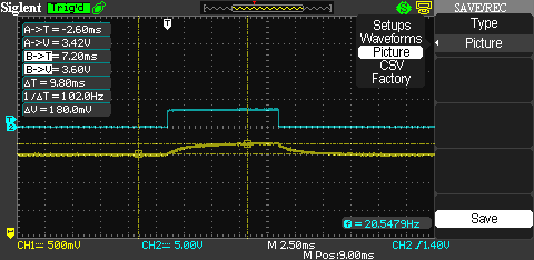
The problem: power on the 3.3v regulator output fluctuates depending on whether the LED strip is ON or OFF. When LEDs are full OFF (pwm 0% duty cycle) I get around 3.29v. When LEDs are ON (pwm 100% duty cycle) I get around 3.5v/3.6v, reaching the max input voltage for the ESP8266 module, wich is unsafe.

  • Wich ever duty cycle I put in between (say %50), I get almost the same signal variation on the 3.3v regulator output.

  • If I unplug the LED strip, the issue disappears and the regultar output stays around 3.3v.

  • If I unplug the ESP module, the problem stays the same. (In that case R8 would be the only load for the regulator)

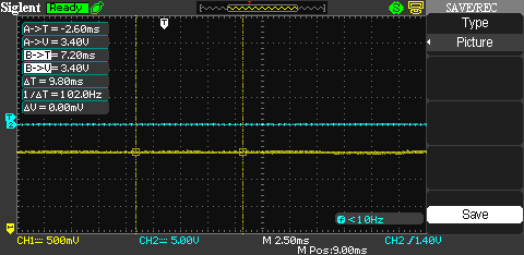
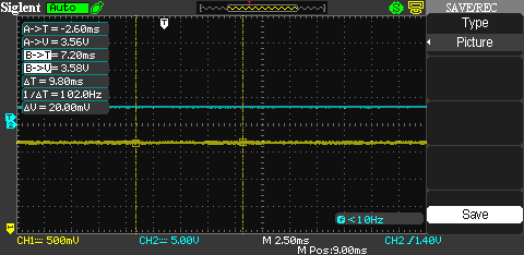
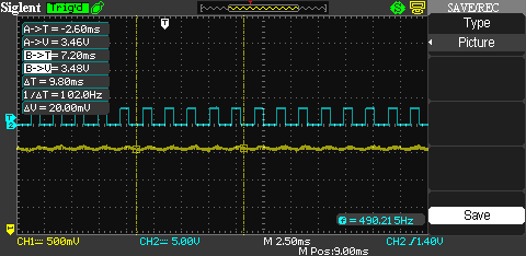
Below are some oscilloscope captures I did. CH1 is the output from the 3.3v regulator. CH2 is signal between R3 and OK3, just for trigger and visualization purpouse.

PWM 0% duty cycle.

PWM 0% duty cycle

PWM 100% duty cycle.

PWM 100% duty cycle

PWM 40% duty cycle.

PWM 40% duty cycle

Strobe effect from 0% to 100% duty cycle. This one shows the voltage difference better.

Strobe effect from 0% to 100% duty cycle

\$\endgroup\$
15
  • \$\begingroup\$ How much current do the LEDs draw? \$\endgroup\$
    – vofa
    Commented Jan 26, 2018 at 18:41
  • 1
    \$\begingroup\$ @leonardog - 10mA is just an output current for which parameters are defined in the datasheet, not a minimum load requirement. Try getting rid of R8, making the caps an order of magnitude smaller (at least), and moving the input from 12V to 5V. \$\endgroup\$
    – vofa
    Commented Jan 26, 2018 at 19:07
  • 2
    \$\begingroup\$ ABSOLUTE MAXIMUM RATINGS Input Voltage (V IN ) .................................................... 7V Reduce C4 to 100uF and connect input to 5V \$\endgroup\$
    – D.A.S.
    Commented Jan 26, 2018 at 19:17
  • 1
    \$\begingroup\$ What's wrong with 3.6v? That's with the ESP's specification right? also, w/o deepsleep, you will always pull more than 10ma from the ESP; no need for a "heater". \$\endgroup\$
    – dandavis
    Commented Jan 26, 2018 at 20:08
  • 1
    \$\begingroup\$ you could use a diode to chop off some of those millivolts if in doubt. a 1000uf cap will "constantize" the load to prevent forward voltage fluctuations under different loads. fwiw, i've used an ESP01 on a LIPO+dioide for ~18month w/o issue. \$\endgroup\$
    – dandavis
    Commented Jan 26, 2018 at 20:17

3 Answers 3

9
\$\begingroup\$

The IRU1015-33 has absolute maximum input voltage of 7 V. You are operating the IC way outside its design parameters. Anything can happen, and 12V on your communication module is a real possibility. Change the regulator to whichever can handle 12V input. Or switch the input of IRU1015 to +5V rail.

\$\endgroup\$
1
4
\$\begingroup\$

As @Ali has swiftly pointed out, you neglected the ABS.MAX.SPECS. in the datasheet, and by a huge margin.

You were also concerned why there might be so much ripple in the 12V from a 4A supply from only one 5m reel of stripLEDs.

  • Load regulation and conduction losses are the main reasons for this.

So what is the dynamic load for reel? ~ 1 Ω

Speculation: Assuming typ. RGB 0.6 Amps/m ...*5m = 3A... * 12V=36W.
If it was a linear R load , R= 12V/3A=4Ω but it's not.
If the current rises linearly from 9 to 12V then it is 3V/3A = 1Ω due to all the series shunt current limiting resistors.

\$\endgroup\$
2
  • \$\begingroup\$ +1 Yep, the OP should definitely check the quality of 12-V input rail and post scope traces. \$\endgroup\$ Commented Jan 26, 2018 at 22:25
  • \$\begingroup\$ Though I guess this behaviour was related to the pointed out issues (max input voltage on the regulator) I found it odd that the voltage before the regulator went up when the LEDs turned on. I would've expected the opposite. \$\endgroup\$
    – leonardog
    Commented Jan 30, 2018 at 18:18
0
\$\begingroup\$

Not knowing how this circuit is wired up, or how much current the LED strip draws...

One thing you may want to check is the integrity of the GND net. Does the voltage at the ground terminal of the regulator stay at zero, or does it increase with LED strip current due to resistive voltage drop along the current return path?

I'm amazed the IRU1015 survives and regulates pretty well at nearly double the abs max input voltage!

\$\endgroup\$
1
  • \$\begingroup\$ Right! Among other things I was having ground issues, wich solved when I properly tied ground rails within the protoboard. Thanks. \$\endgroup\$
    – leonardog
    Commented Jan 30, 2018 at 18:01

Your Answer

By clicking “Post Your Answer”, you agree to our terms of service and acknowledge you have read our privacy policy.

Not the answer you're looking for? Browse other questions tagged or ask your own question.