I started working with the LT1990 Differentiel amplifier. In the datasheet, it's stated that it needs a 1.25V voltage reference. I made some research and I found the TLVH431 Low-voltage adjustable precision shunt regulators but I didn't understand how it works and how from an input voltage I can have 1.25V voltage reference ? Can someone explain to me how it works
-
\$\begingroup\$ Did you read the data sheet for the TLVH431? \$\endgroup\$– ColinCommented May 8, 2018 at 14:23
-
\$\begingroup\$ of course i read the datasheet but it's my first time working with voltage reference and the TLVH431 so i don't have any idea \$\endgroup\$– Karim OuazaaCommented May 8, 2018 at 14:27
-
2\$\begingroup\$ All the information is in the datasheet, including the feature description, which tells you how it works. \$\endgroup\$– MCGCommented May 8, 2018 at 14:39
2 Answers
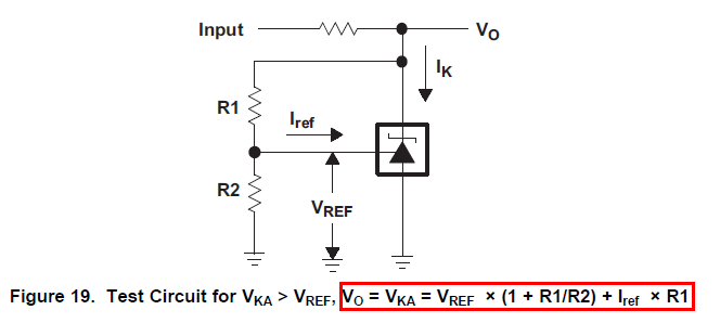
The internal ref voltage for a TLVH431 is 1.24 volts but this can vary a bit between about 1.2 volts and 1.28 volts so be aware of this. That reference voltage will appear at the reference input when you have feedback in place. If you use resistors forming a potential divider to the REF input then the voltage on the anode is: -
Picture taken from the data sheet.
-
\$\begingroup\$ so for example my input voltage is 5V and i choose R1 and R2 so that in the output of the voltage devider is 1.24V(Vref) and with that equation i can calculate the needed resistor so that i can get an output voltage equal to 1.25V \$\endgroup\$ Commented May 8, 2018 at 14:39
-
2\$\begingroup\$ Yes you can but be aware that it isn't worth doing this because the device has an accuracy that is worse than the 10 mV you wish to correct for. If you need a precise 1.25 volts then use a better device with an initial tolerance much better than +/- 3% (and there are many, many superior devices that will produce sub 1% 1.25 volts). \$\endgroup\$– Andy akaCommented May 8, 2018 at 14:42
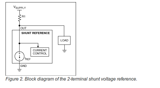
In addition to Andy aka's description of the TLVH431, some general information about Shunt References taken from a Maxim Appnote
Shunt Reference A shunt reference has two terminals, OUT and GND. It is similar in concept to a zener diode, but has much better specifications. Like a zener diode, it requires an external resistor and operates in parallel with its load (Figure 2). It can be regarded as a voltage-controlled current source between the OUT and GND terminals. Regulation is achieved by adjusting the current level so that VSUPPLY minus the drop across R1 equals the reference voltage at OUT. As an alternate description, the shunt reference maintains a constant voltage at OUT by forcing the sum of load current and current through the reference to be constant. Shunt references have these characteristics:
Given an R1 appropriately sized for power dissipation, the shunt reference imposes no limit on the maximum power-supply voltage.
The power supply delivers the same maximum current regardless of load. Supply current flows through load and reference, dropping just the right voltage across R1 to maintain the OUT reference voltage.
Maxim application note 4003


