0
\$\begingroup\$

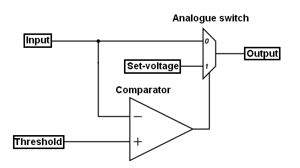
Regarding an answer of my previous question, I want to use the following topology:

enter image description here

When the input is below the threshold, the comparator output is HIGH and the Analogue switch above outputs the set voltage. However if the input exceeds the threshold, the switch will output the input ect.

If I use this analog switch DG417(which I never tried before), does anybody know which pin corresponds what here?

enter image description here

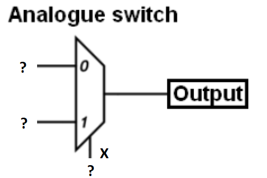
Considering the above diagram for the switch, what does 0, 1 and X on the analog switch above correspond in the datasheet D, S1, IN, VL, S2?

\$\endgroup\$

1 Answer 1

1
\$\begingroup\$

You will need the DG419 SPDT switch. The DG417 is an SPST switch, which won't do for your application.

For the DG419, D (pin 1) would be your output. S1 (pin 2) is connected to D when IN (pin 6) is Low. S2 (pin 8) is connected to D when IN is High.

\$\endgroup\$
2
  • \$\begingroup\$ Btw what is VL pin? Should it be grounded in my case? I will use single supply. \$\endgroup\$
    – user16307
    Commented May 28, 2018 at 19:27
  • \$\begingroup\$ The "Electrical Characteristics" table in the datasheet shows VL connected to +5V. Under "Application Information", it says VL should be connected to +5V for the control input to be TTL-compatible, or to V+ for use with higher-voltage CMOS. When in doubt, read the datasheet! For single-supply operation, V+ must be 10 - 30 Volts. \$\endgroup\$ Commented May 28, 2018 at 19:35

Your Answer

By clicking “Post Your Answer”, you agree to our terms of service and acknowledge you have read our privacy policy.

Not the answer you're looking for? Browse other questions tagged or ask your own question.