1
\$\begingroup\$

I have constructed transimpedance amplifier in the hopes to achieve both high-gain (5kΩ) and high-bandwidth (50MHz) performance using the FGA21 photodiode, the OPA657 Op-Amp and the 2N2369 Transistor. Key specifications include:

  • Gain Bandwidth Product: GBW = 1.6GHz
  • Photodiode Capacitance: Cd > 100pF

To extend the amplifier bandwidth I have implemented the bootstrap architecture, as illustrated in the figure below: Bootstrapped TIA Circuit Layout
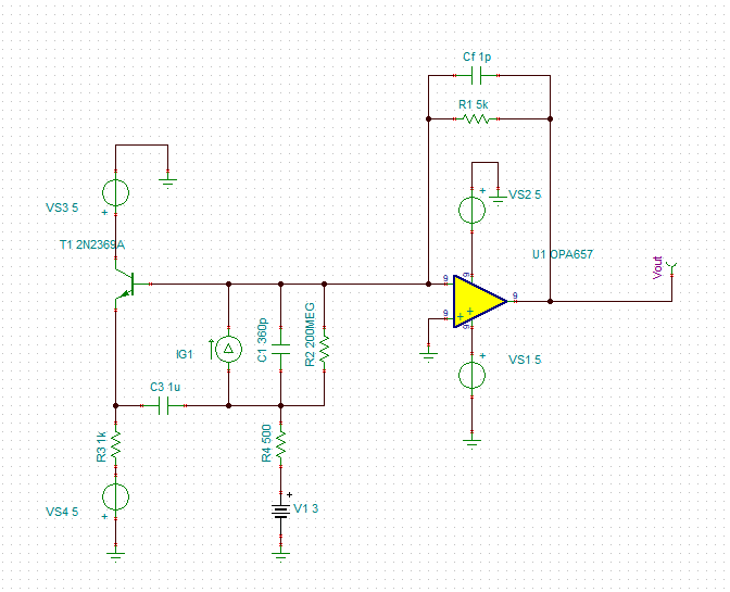
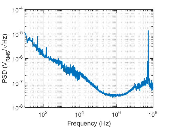
Here the photodiode is replaced by the equivalent circuit. This circuit has been constructed and to confirm stable operation a voltage noise measurement was recorded:

Output Voltage Noise

This shows a bright noise feature at 50MHz which is problematic as it is near the frequency band of interest for our application. To explore this behaviour further the detector output was measured on an oscilliscope and a clean +120mV DC output was observed, which is consistent with the base current provided by the transistor. When the photodiode is illuminated the output starts decreasing as expected from an inverting amplifier, however, as it approaches 0V the output begins oscillating dramatically (+-500mV amplitude) at the resonance frequency of 50MHz. Suggesting this resonance feature is being excited.

My only explanations are the following:

  • The 2N2369 transistor is not fast enough to ensure stability at 50MHz
  • And/or when the photodiode is illuminated the photodiode current counteracts the base current and switches the transistor off when it reaches an appropriate level, reducing the gain at 50MHz even further and causing dramatic oscillations.

However, I am not convinced about either of these answers as the SPICE model of this circuit does not predict resonances at these frequencies. Any ideas on the cause of/ solution to these problems would be greatly appreciated.

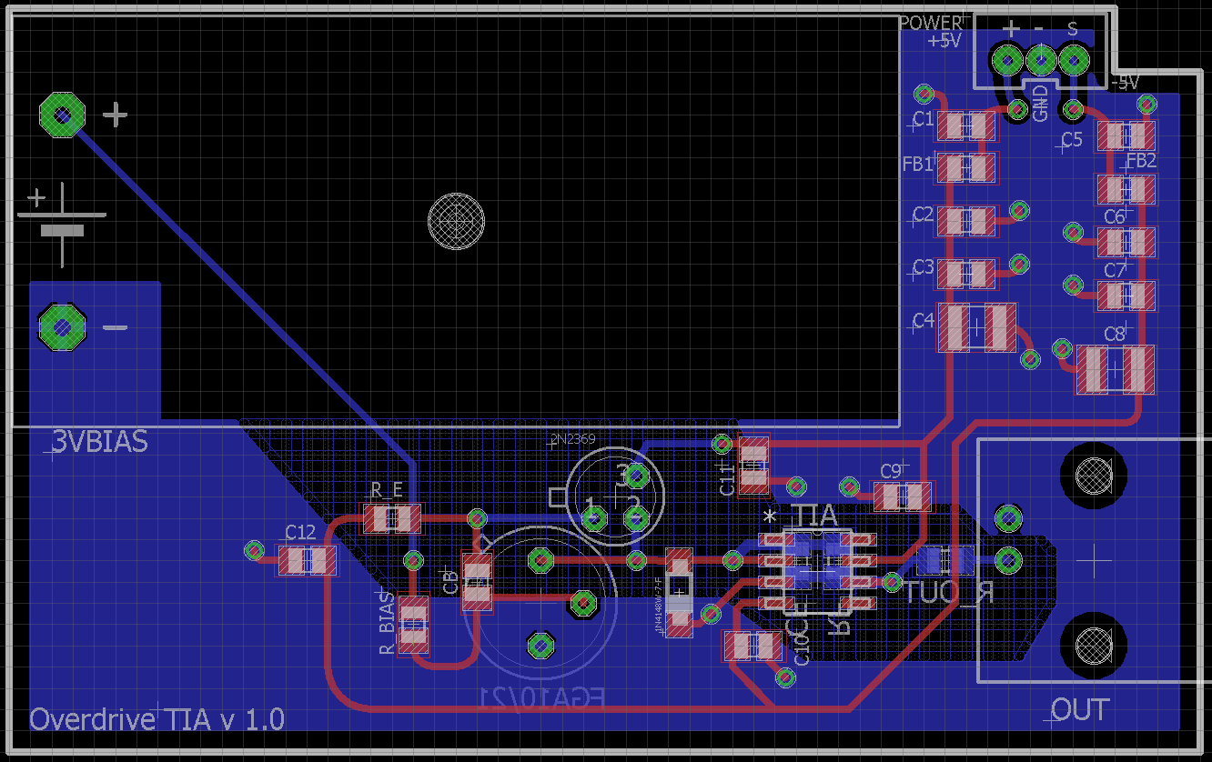
(EDIT: Please find the board layout below for reference) enter image description here

\$\endgroup\$
5
  • \$\begingroup\$ Have you tried increasing Cf to improve stability? Stability is very dependent on the total capacitance to ground at the input, so if your actual input capacitance is higher than in simulations (eg. due to the bootstrap circuit not working perfectly, layout issues, etc.) it could lead to instability. \$\endgroup\$
    – Sven B
    Commented May 29, 2018 at 9:04
  • \$\begingroup\$ Thanks for your suggestion Sven, I haven't tried increasing the feedback capacitor past 1pF. Having said that based on some of my previous work with the standard TIA configurations (i.e. non bootstrapped) with the same photodiode and op-amp the noise peaks tend to be at ~10MHz if the amplifier is not properly compensated. I could try increasing Cf further to examine the effect on the 50MHz peak but I fear that this will only cut into my bandwidth further and offset the potential improvements of the bootstrapped configuration. \$\endgroup\$
    – J-Pease
    Commented May 29, 2018 at 23:35
  • \$\begingroup\$ I read that you're targeting 50MHz. This is approx. \$BW\approx\frac{1}{2\pi R_f C_f} \$ if your open loop gain is high enough. So yours is around 32GHz. You can increase \$C_f\$ until 636pF for a BW of 50MHz. \$\endgroup\$
    – Sven B
    Commented May 30, 2018 at 4:53
  • \$\begingroup\$ Hi Sven, I believe you've made an error in your calculation, that will give a bandwidth of 50kHz not 50MHz. \$\endgroup\$
    – J-Pease
    Commented May 30, 2018 at 5:42
  • \$\begingroup\$ Yes, you're right, my bad. I used 1pF=1e-15F, but that is obviously incorrect. I should refrain from posting when I just woke up ;-) \$\endgroup\$
    – Sven B
    Commented May 30, 2018 at 5:47

2 Answers 2

1
\$\begingroup\$

I'm not 100% convinced the OPA657 can produce great results when it is operated using a bootstrap circuit as you have. The bootstrap performs one primary function and that is to "convince" the TIA circuit that the photodiode self-capacitance is much smaller.

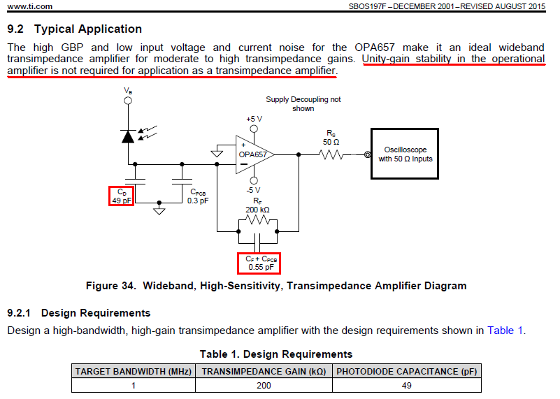
Having a smaller photodiode capacitance means that noise-gain is significantly reduced and you can "afford" to reduce the feedback capacitor in order to get more bandwidth. However, the OPA657 is compensated internally for gains of ten and this means at gains of near unity it could become unstable or show signs of excessive noise. Consider this section of the data sheet: -

enter image description here

This is for a conventional un-bootstrapped TIA and although you may think it to be unity gain, it isn't. The "true" gain at high frequencies is roughly 49 pF / 0.55 pF = 90. I'm not talking about Vo/Iin here - I'm talking about noise gain and the noise gain is about 90 at high frequencies. However, this is pegged-back by the open loop gain characteristic to about 8 (see figure 9.2.3).

In other words it has a gain of round about ten i.e. the point that the internal compensation is optimized for.

Bottom line is that I'm pointing at this and saying that this op-amp is not suited for use as a bootstrapped TIA but there could be other reasons such as poor decoupling on the supply rails, bad PCB layout etc..

\$\endgroup\$
5
  • \$\begingroup\$ Thank you so much for your detailed response Andy, that is definitely something I had not considered during the design of this circuit. I may try using the LMH6624 instead of the OPA657, it has a similar GBW and looking through the spec sheet it does not appear to be internally compensated. I have also inserted an image of the PCB layout in the main post, I have tried to follow many of the suggested design techniques that I've found online but there are likely areas I can improve on! \$\endgroup\$
    – J-Pease
    Commented May 29, 2018 at 23:54
  • \$\begingroup\$ Hi Andy, after swapping the OPA657 for the LMH6624 I see much better noise performance, there is still a slight peak at 50MHz but it no longer dominates the spectrum and the output is now stable across it's full dynamic range. Thanks again for your help. \$\endgroup\$
    – J-Pease
    Commented May 30, 2018 at 7:27
  • \$\begingroup\$ @J-Pease it's probably luck that makes the LMH work better - if you look at the DS it says stable for gains > 10 on page 1 so please be aware that you can likely expect problems with it. This photodiode wizrd from ADI may be useful to you even if it's only in selecting a better / more reliable op-amp. I would also use a sim tool for establishing quickly whether op-amp A or B are better. Plus also look up using a JFET as the bootstrap device - BF862 springs to mind. \$\endgroup\$
    – Andy aka
    Commented May 30, 2018 at 8:03
  • \$\begingroup\$ Hi Andy, what advantages would there be for using the JFET instead of a standard BJT transistor in the bootstrap? I've had a look in literature and some bootstrapped amplifiers have used the BF862, however they do not provide reasons as to why this device was chosen. \$\endgroup\$
    – J-Pease
    Commented May 31, 2018 at 0:46
  • \$\begingroup\$ @J-Pease high frequency operation may be an advantage and certainly if you need DC accuracy then the JFET requires no bias current. \$\endgroup\$
    – Andy aka
    Commented May 31, 2018 at 8:31
1
\$\begingroup\$

One, ah, base you may need to cover : it's surprisingly easy to build an accidental Colpitt's oscillator with a general purpose NPN transistor.

The usual cure for this is a "base stopper" resistor - a smallish resistor (start with 100R and reduce if you can) immediately in series with the base (as close to it as physically possible, to minimise capacitive coupling into the base).

As base current is low, this should have a minimal effect on wanted signals.

\$\endgroup\$
1
  • \$\begingroup\$ Thanks for the very helpful suggestion Brian, I had concerns that parasitic processes may be the cause of this, especially due to the fact that this feature is at such a high frequency and is quite high Q. However, as I'm sure you're aware it is often difficult to tie down where these parasitic processes are arising. I will solder in a small resistor and provide an update if this is the cause of my problem. \$\endgroup\$
    – J-Pease
    Commented May 29, 2018 at 23:40

Your Answer

By clicking “Post Your Answer”, you agree to our terms of service and acknowledge you have read our privacy policy.

Not the answer you're looking for? Browse other questions tagged or ask your own question.