0
\$\begingroup\$

Okay,

I'm trying to monitor current going to a device, and in case current is drawn, light a led and provide a low signal (<5V) to a microcontroller.

The current goes through a half-ohm resistor and the voltage difference is amplified by AD8210. Output of the amplifier is compared to a reference value set by a potentiometer using a LP311. Reference value is set by hand so that the led illuminates when the load is active.

This far everything goes fine, but trying to read the status to a microcontroller won't work, as LP311's collector stays at ~11V even when active.

My only idea so far has been that the output transistor is not saturated. However, increasing the load current and therefore increasing the comparator input difference should then bring collector voltage lower, but this was not the case.

So, why is emitter-collector voltage so high? I was expecting it to be 1V or less.
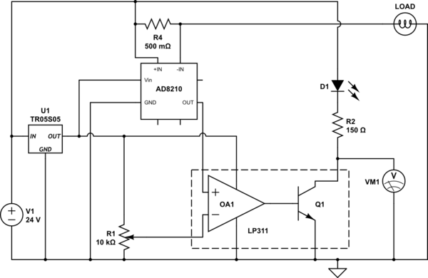
schematic

simulate this circuit – Schematic created using CircuitLab

\$\endgroup\$
1
  • \$\begingroup\$ What are the voltages you read at each of the LP311 pins when the LED is illuminated? You should also worry about the voltage you will be connecting to the microcontroller when the LED is dark...it will be even higher than 11V. \$\endgroup\$ Commented Jun 25, 2018 at 12:29

2 Answers 2

1
\$\begingroup\$

You are trying to draw too much current from the output. If your supply is 12V then the current would be 60 or 70mA, which is far higher than the low power comparator can supply. If your supply is higher, it's even worse.

You say:

However, increasing the load current and therefore increasing the comparator input difference should then bring collector voltage lower, but this was not the case.

But this is not true, the output current will be limited by the available base current (which has more to do with the internal biasing networks), which will not increase for differential inputs beyond a few mV. With a 5V supply (4.5V in the specifications) it is only guaranteed to sink 1.6mA with a defined maximum \$\text V_{OL}\$.

enter image description here

So add a buffer for the LED and all should be well.

\$\endgroup\$
2
  • \$\begingroup\$ Ah, yes, I'm a brick. 0.147A is not 14,7mA no matter how many times you check it. Regarding my statement about increasing the input difference: it would be true if my starting point happened to be within few mV, correct? \$\endgroup\$
    – KLuuppo
    Commented Jun 25, 2018 at 12:48
  • \$\begingroup\$ @KLuuppo The datasheet for the LP311 is inexplicably sketchy- no typical curves etc.. If it's similar to the venerable LM311 the transition takes maybe 200uV- it's dwarfed (if I can still say that) by the offset voltage, so they roll them both into one number - note #7. \$\endgroup\$ Commented Jun 25, 2018 at 13:57
0
\$\begingroup\$
  1. For linear DAC controlled brightness on power LEDs start matching LED Vf string to Vcc-1 approx. or more with suitable power FET or NPN that can dissipate Vdrop *I * Rja (thermal resistance) < 50’C. ( for Ta= 40’C max on board as absolute max , not ideal.

  2. Use DAC V scaled down to 50mV max and use current sense R on emitter or source to compare Vdac with I-LED

  3. Then chose OA with PNP inputs that sense below Vee or down to 0mV with low Vio.

This becomes an efficient current source and there are many IC’s which do this already.

Vce(sat)/Io~ Rce = 200mV/1.6mA on LP311 is approx 125 Ohms minimum is too high for 60 mA (1W) and higher Vce only gets worse and will get too hot

or LP312 fails from internal current limiting and thus Vce stays high. Poor choice and no design specs makes it fail.

\$\endgroup\$

Your Answer

By clicking “Post Your Answer”, you agree to our terms of service and acknowledge you have read our privacy policy.

Not the answer you're looking for? Browse other questions tagged or ask your own question.