1
\$\begingroup\$

The Widlar current source is illustrated below:
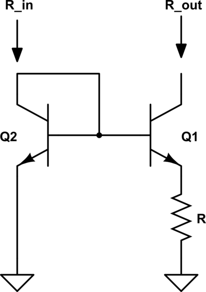
schematic

simulate this circuit – Schematic created using CircuitLab

The small-signal AC model is shown below:
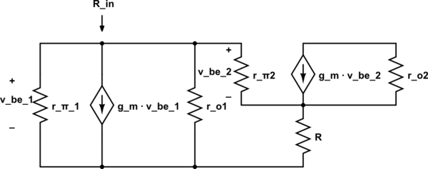
schematic

simulate this circuit

I know that if the Early voltage is assumed to be infinite, then the input resistance \$R_{in} = r_{\pi} + \left(\beta + 1\right)R\$. But how does it change (or not change) when the Early voltage is taken into account (i.e., when \$r_{o}\$ is not infinitely large?

\$\endgroup\$
1
  • \$\begingroup\$ A quick note: The input impedance is simply \$R_{in}=g_{m_1}^{-1}||r_{o}^{1}||R_{in}^{Q_2}\$, where \$R_{in}^{Q_2}=[r_{e_2}+R][\beta+1]\$. If \$r_{o_1}\$ is large compared to \$g_{m_1}^{-1}||R_{in}^{Q_2}\$, then you can neglect it and write \$R_{in} \approx g_{m_1}^{-1}||R_{in}^{Q_2}\$, but since \$R_{in}^{Q_2}\$ is typically large compared to \$g_{m_1}^{-1}\$, the input resistance simply reduces to \$R_{in}\approx g_{m_1}^{-1}\$. \$\endgroup\$
    – dirac16
    Commented Jul 22, 2018 at 16:48

1 Answer 1

-1
\$\begingroup\$

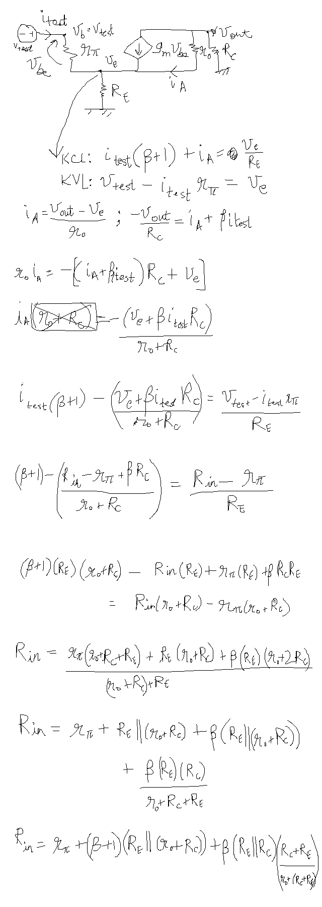
The answer is as described in the following graphic: This needs to be transcribed, but I don't have the time to do it.

\$\endgroup\$
1
  • 2
    \$\begingroup\$ Hi, thank you for your effort. Please note that you can use the schematic drawer tool when you write your answe. Further, Equations can be written as well. Please use these tools when you write any answer/question in the future. \$\endgroup\$
    – Hazem
    Commented Jul 22, 2018 at 17:43

Your Answer

By clicking “Post Your Answer”, you agree to our terms of service and acknowledge you have read our privacy policy.

Not the answer you're looking for? Browse other questions tagged or ask your own question.