0
\$\begingroup\$

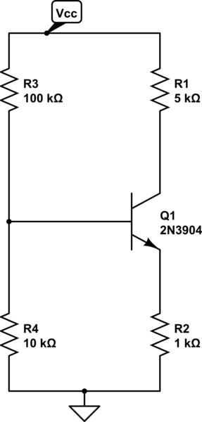
Consider the common emitter amplifier in the schematic:

schematic

simulate this circuit – Schematic created using CircuitLab

The input impedance is \$Z_{in}=[(R3\left | \right |R4)\left | \right |\beta(r_e + R2)]\$

Now can I just go on increasing the input impedance by just increasing the values of the resistors or is there some limit to this?

\$\endgroup\$

1 Answer 1

4
\$\begingroup\$

The answer is ... it depends what else you want to achieve.

Increasing all the resistors will increase the input impedance.

The limit starts to come in where the transistor loses gain at very low currents.

As R4 is dominating the circuit as drawn (assuming reasonable hFE like 100 or so), sorting R4 will give you the most bang for buck.

In order to increase the AC input impedance, without disturbing the DC bias, you could bootstrap R4, by splitting it into two parts, say two 5k resistors in series, and connecting a capacitor from Q1 emitter to the mid point. As Q1 emitter follows the base with a gain of 0.99ish, that will all but eliminate the signal current that gets conducted down R4.

With R4 bootstrapped, R3 now dominates. You could replace R3 and R4 potential divider by a single resistor from a point of the right voltage, bootstrapped to Q1 emitter. That eliminates R3 and R4 for signals.

Replacing Q1 with a darlington transistor for much higher hFE will reduce the R2 term.
\$\endgroup\$
2
  • \$\begingroup\$ Replacing Q1 with a darlington reduces the R2 term, but R4 is almost certainly the one you need to go after to make any real improvement. \$\endgroup\$
    – The Photon
    Commented Jul 31, 2016 at 16:42
  • \$\begingroup\$ @ThePhoton ... after bootstrapping R4 and R3 \$\endgroup\$
    – Neil_UK
    Commented Jul 31, 2016 at 17:05

Your Answer

By clicking “Post Your Answer”, you agree to our terms of service and acknowledge you have read our privacy policy.

Not the answer you're looking for? Browse other questions tagged or ask your own question.