An actual diode is limited by the laws of Physics [tm]. Actual voltage will depend on current and voltage and device used but, as a guide, under very light loading a Schottky diode may manage somewhat under 0.3V but this typically rises to 0.6V + as loading approaches maximum allowed. High current devices may have forward voltage drops of well over 1V. Silicon diodes are worse by a factor of two to three.
Using a MOSFET in place of a diode provides a resistive channel so that voltage drop is proportional to current and can be much lower than for a diode.
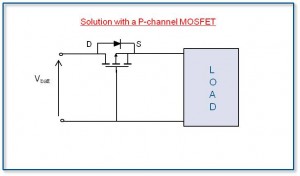
Using a P Channel MOSFET as shown below causes the MOSFET to be turned on when the battery polarity is correct and turned off when the battery is reversed. Circuit and others from here I have used this arrangement commercially (using the mirror image arrangement with an N Channel MOSFET in the ground lead) for a number of years with good success.
When the battery polarity is NOT correct the MOSFET gate is positive relative to the source and the MOSFET gate source 'junction' is reverse biased, so the MOSFET is turned off.
When the battery polarity is correct the MOSFET gate is negative relative to the source and the MOSFET is correctly biased on and load current "sees" on the FET Rdson = on tresistance. How much this is depends on the FET chosen but 10 milliohms FETs are relatibely common. At 10 mOhm and 1A you get only 10 milli-Volt drop. Even a MOSFET with Rdson of 100 milliohm will only drop 0.1 Volt per amp carried - far less than even a Schottky diode.

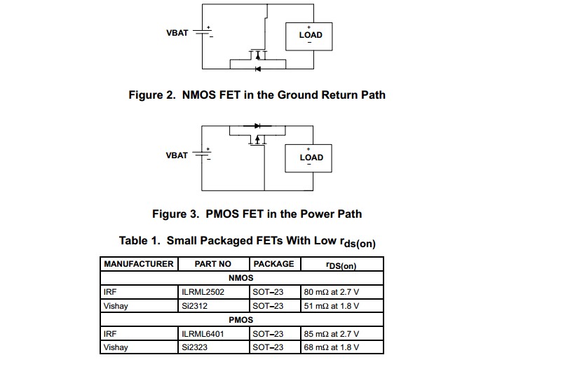
TI application note Reverse current / battery protection circuits
Same concept as above. N & P channel versions. MOSFETs cited are examples only. Note that the gate voltage Vgsth needs to be well below the minimum battery voltage.


