0
\$\begingroup\$

I've been studying inductors and wanted to understand the behavior as a circuit is switched off just like the one below, when the transistor is normally conducting and suddenly is turned off by, say, a microcontroller signal. I know it's weird but please, do not consider the Protection Diode across it, I could neither find a better image nor design one circuit here since I'm asking it via cell phone. enter image description here
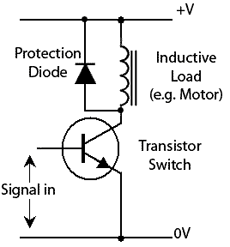
Thus, I know that V=L*di/dt and it's the induced voltage formula across an inductor. I know it's going to yield a large voltage as it's quickly turned off, because di/dt is going to be a huge factor. Also, the current which is supposed to flow through the inductor as t-> (infinite) is I=(V+) /R where R is the coil resistance. In addition to that, I know that as the transistor is turned off, the current in an inductor cannot instantly change, so it's going to be (V+) /R in the very first moment the transistor is off, and assuming it'll have a really high resistance when off, the voltage across the inductor should be large in order to try to maintain the current flowing just like before.

My point is I get confused on how to think correctly about it. What is actually the correct way to think? The way by which di/dt is large and so will be the voltage across the inductor or the way by which the current will try to be kept constant and as the transistor is going to be a huge resistance when turned off, the voltage across the inductor will then be large?

Thank you for any help.

\$\endgroup\$
2
  • \$\begingroup\$ Both ways are equally valid. \$\endgroup\$
    – Andy aka
    Commented Jul 27, 2018 at 11:05
  • \$\begingroup\$ The various capacitances will end up storing the energy, if the diode is not there. Given Energy_cap = 0.5 * C * V^2 = Energy_Coil = 0.5 * L * I^2, and assuming 100pF on the collector, have a fun time predicting the (very high) voltages to expect. \$\endgroup\$ Commented Jul 29, 2018 at 5:17

1 Answer 1

1
\$\begingroup\$

Hopefully, this will explain how there are two initial conditions. The first one is obvious (the current taken by the coil when the transistor was conducting) and the initial condition of di/dt when the transistor open-circuited.

When the transistor open-circuits the static initial condition for the inductor is "so-many amps" flowing. That intial condition will generate a large voltage (theoretically and simplistically infinite) but we know parasitic (or intentional clamp) components restrict us to hundreds of volts.

Following the open-circuit event and making the simplistic assumption that the voltage stays constant for some time afterwards (assume there was a zener diode clamp at 100 volts for instance), we know that di/dt = V/L.

So we know the static initial condition (let's say 100 mA), we know V (100 volts) and we hopefully know the inductance (say 100 mH). To maintain this situation current falls from 100 mA towards zero at a rate of 100 volts / 100 mH = 1000 amps per second or 1 A per millisecond.

This means that after 100 micro seconds the current hits zero and there is no energy left in the inductor - it's all burnt off by the zener. At this point the voltage instantly collapses to zero volts.

I know it's weird but please, do not consider the Protection Diode across it

Without a protection diode and in the absense of parasitic capacitance in the transistor or inductor then the voltage is of course infinite and the event lasts for zero time. I don't find that to be a helpful scenario but you asked for it!

\$\endgroup\$
3
  • \$\begingroup\$ It has been a great help @Andy. I think I have taken the point. And yeah I know it's weird taking the diode out, but it was just so I could understand the inductor behavior only. But just so I have really gotten the diode idea: the diode clamp (intentional clamp) would be put in parallel with the coil right? But assuming the inductor is generating a voltage higher than 100V, wouldn't this voltage be across the diode regardless of its zener voltage? In my understanding to clamp there should be a resistance to hold part of the voltage so the diode can clamp at 100V isn't that right? \$\endgroup\$ Commented Jul 27, 2018 at 13:08
  • \$\begingroup\$ The inductor isn't generating a hard 100 volts - in effect - it's generating the initial current (soft in voltage terms) and whatever that current flows into defines the voltage. The zener diode clamp idea isn't always preferable to a regular diode clamp across the coil. I was using it as an idea-tool to provoke understanding. Anyway it can be used but would go across CE of the transistor. \$\endgroup\$
    – Andy aka
    Commented Jul 27, 2018 at 13:15
  • 1
    \$\begingroup\$ I was thinking it could be across CE when first thought. Anyway, I have understood I guess, thank you very much Andy! \$\endgroup\$ Commented Jul 27, 2018 at 14:05

Your Answer

By clicking “Post Your Answer”, you agree to our terms of service and acknowledge you have read our privacy policy.

Not the answer you're looking for? Browse other questions tagged or ask your own question.