1
\$\begingroup\$

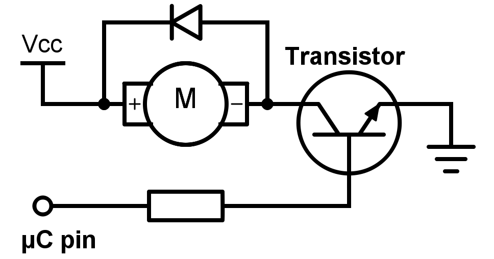
A diode is used parallel to the motor (or inductive load) in order to prevent damage to the switch because of back-emf voltage. Now, that back-emf voltage actually produces a current and by using a fly-back diode, that current is going into the voltage source which maybe a battery.

1- Is there any consideration one should take into account because current sometimes goes into the source?
2- What kind of sources or battery chemistries can and can not tolerate such current?

https://www.norwegiancreations.com/wp-content/uploads/2015/12/schemeit-project17.png

\$\endgroup\$
3
  • 1
    \$\begingroup\$ It's actually the current that produces the back emf voltage. Knowing that, would that make your question null in your eyes? \$\endgroup\$
    – Andy aka
    Commented Jul 29, 2018 at 15:35
  • \$\begingroup\$ @Andyaka No, Actually my problem was placing V_backemf above transistor (not inside the loop). It makes sense now. \$\endgroup\$ Commented Jul 29, 2018 at 15:53
  • \$\begingroup\$ You can also read this article from wiki en.wikipedia.org/wiki/Flyback_diode \$\endgroup\$
    – dirac16
    Commented Jul 29, 2018 at 16:02

2 Answers 2

7
\$\begingroup\$

schematic

simulate this circuit – Schematic created using CircuitLab

Figure 1. OP's schematic redrawn with switch replacing the transistor and normal current flow from top to bottom (as is standard in schematics).

Now it should be clear that when SW1 opens no current can flow into the battery positive as no "return" current can flow from the battery negative.

Instead, think of the inductance as trying to maintain the current in the direction it was flowing. With the diode present it will circulate from the bottom of the motor back to the top until it decays to zero due to the power loss in the diode and the motor winding resistance.

Your concern is valid if regenerative braking is required. In this case the generated power is passed back to the battery (or power supply). The usual way of dealing with this in variable speed drives or servo drives is to monitor the DC bus voltage and if it exceeds a certain voltage to switch in a load resistor to burn off some power. But that's a different question ...

\$\endgroup\$
4
\$\begingroup\$

It's not going into the voltage source. The current circulates through the diode and motor coil resistance until the energy stored in the inductance is dissipated.

\$\endgroup\$
2
  • \$\begingroup\$ At least most of it. \$\endgroup\$
    – winny
    Commented Jul 29, 2018 at 15:29
  • \$\begingroup\$ which part isn't? \$\endgroup\$ Commented Jul 29, 2018 at 17:49

Your Answer

By clicking “Post Your Answer”, you agree to our terms of service and acknowledge you have read our privacy policy.

Not the answer you're looking for? Browse other questions tagged or ask your own question.