-2
\$\begingroup\$

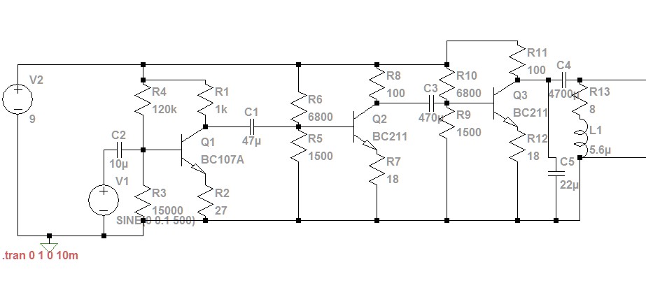
All photos, schematics and the ltspice simulation file are in the folder.

https://drive.google.com/folderview?id=1N1yKGnoWQoaGsuHla0DwJwF36_21ZBgX

Hello!

I have made a simple class A amplifier, but it seem to be turning sine signals into square wave ones. What could be the cause of this? Is this an good design?

I added a smoothing cap in parralel and it smoothed the lower freq. and trianglelized the higher freq. I know that the transistors are pretty ancient, but I have so much of them lying around.

The photos are waveforms of the output of the amp, various frq. were fed and some are with and without the smoothing cap.

\$\endgroup\$
19
  • 5
    \$\begingroup\$ Please edit your question to include enough information - that means at least the schematic and waveform images - inline with your question. Not many of us will follow links to understand your question and adding them inline means your question may be useful to others even when the link dies. Use screengrabs rather than photographs of a monitor. \$\endgroup\$
    – Transistor
    Commented Aug 4, 2018 at 18:13
  • 1
    \$\begingroup\$ obviously, too much input x gain \$\endgroup\$
    – D.A.S.
    Commented Aug 4, 2018 at 18:27
  • 1
    \$\begingroup\$ They're saying the product of the input and the gain is too large, it's clipping. Attenuate the input, or reduce the gain, or both. \$\endgroup\$
    – Colin
    Commented Aug 4, 2018 at 19:20
  • 2
    \$\begingroup\$ @thegamebusterpl Did you design your amplifier? Or did you find it somewhere? (The reason I ask is that you seem pretty clueless and it leaves me wondering.) If you designed it, please add your design thoughts (and calculations as appropriate), as well. \$\endgroup\$
    – jonk
    Commented Aug 4, 2018 at 19:21
  • 1
    \$\begingroup\$ Do you want a class-A design? Or are you just going that direction because you think it is somehow easier? (Look over amplifier class of operation, if you aren't sure.) You have a 9 V supply. You can get maybe 1 W power output into 8 Ohms with it (without going to a bridge-tied design.) Do you have a power goal? Or any specs, at all, actually? Does the supply need to be 9 V? Does it need to have three stages? Etc. What are your constraints? \$\endgroup\$
    – jonk
    Commented Aug 5, 2018 at 1:09

1 Answer 1

1
\$\begingroup\$

OK you mislead us a tad because what starts as a simple transistor amplifier ends up with an unusually high Q ~14.37Hz Bandpass filter. THe impedance of the 5.6uF at resonance is only ~ 1/2 Ohm and with a 100 Ohm collector shunt the impedance ratio or Q is 200.

So unless you have exactly the right caps values and input stable frequency ( like Jim Cutler Maine VLF) you wont get much signal at all. since the emitter is 18 Ohms + Rbe your gain will be around 100/20=5.

This gives an overall gain of 2x , 4x , 4x = 32, not excessive but rather insufficient.

Since you are getting a square wave , you must be using a signal gnerator , you may have have the 22uF cap for C5 on the emitter rather than the collector which makes a huge difference on Collector/Emitter impedance ratio for gain.

enter image description here

\$\endgroup\$
2
  • \$\begingroup\$ As base resistors you mean r4 and r3? \$\endgroup\$ Commented Aug 4, 2018 at 22:17
  • \$\begingroup\$ Yes Did you have any idea if this is for a VLF Rx?, Normally R_base is equiv to about 50xRe for R ratios or make Re=2% of Rbase then add a cap across it for gain. There are many improvements that could be made \$\endgroup\$
    – D.A.S.
    Commented Aug 4, 2018 at 22:18

Not the answer you're looking for? Browse other questions tagged or ask your own question.